How Linear and Switching Power Supplies Work
Linear and Switching Power Supplies (SMPS – switched mode power supply) are the two primary types of supplies found in Appliances, Televisions, and HVAC units., The respective design and operation of Linear vs. Switching Power Supplies is quite different. Figure 1 shows an actual linear power supply for an oven control.
*CLICK HERE FOR THE FREE ELECTRICITY MICRO-COURSE FOR APPLIANCE TECHNICIANS*
*CLICK HERE TO DONATE*
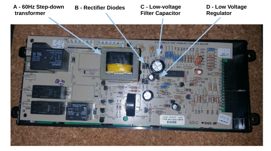
Figure 2 below shows the corresponding block diagram for the above Linear Power Supply. The list below breaks out the illustrated functional blocks:
A) A large 60Hz Step-down transformer is used to step the 120VAC RMS to 12VAC RMS.
B) 12VAC RMS is full-wave rectified into an unfiltered pulsing voltage with a value of 16.8 volts peak. This is because the peak value of 12V RMS is multiplied by 1.41 to obtain the peak value. In practicality, it will be a volt or so less due to the rectifier diodes’ cumulative voltage drops.
C) The unfiltered pulsing 16.8 volts peak voltage is filtered in this block by capacitors. This results in a 16.8 volts DC when no load is placed on it.
D) This final block has linear style regulators that fine tune the 16.8 volts DC into regulated 12V and 5V DC voltages.

Advantages and Disadvantages of a Linear Power Supply
Both power supply types have their advantages and disadvantages.
Linear Power Supply Advantages
1. Simple to design – fewer components
2. Low noise – low frequency
3. Stable – resistant to voltage spikes
4. Lower failure rate of filter capacitors than switching supplies
Linear Power Supply Disadvantages
1. Expensive – step down transformer is costly due to its relative size.
2. Heavy – step down transformer is large and heavy
3. Inefficient – waste heat from transformer and linear regulators at secondary.
Linear Power Supply Failures and Troubleshooting
Linear supplies are relatively stable and don’t fail as often as switching supplies.
1, Sometimes an over voltage condition can cause the rectifier diodes (Block B) on the supply secondary to short out. This will commonly cause an over current condition that blows a fuse on the primary side.
2. Although the filter capacitors (Block C) on linear supplies are large relative to their current requirements, they sometimes do fail. If so, the voltage won’t be filtered well and the average DC output voltage will drop. Using an ESR meter will help in identifying failed electrolytic capacitors.
3. The linear regulators (Block D) on a the supply’s secondary can fail due to over current situations or simply because they dissipate a lot of heat.
Switching Power Supply
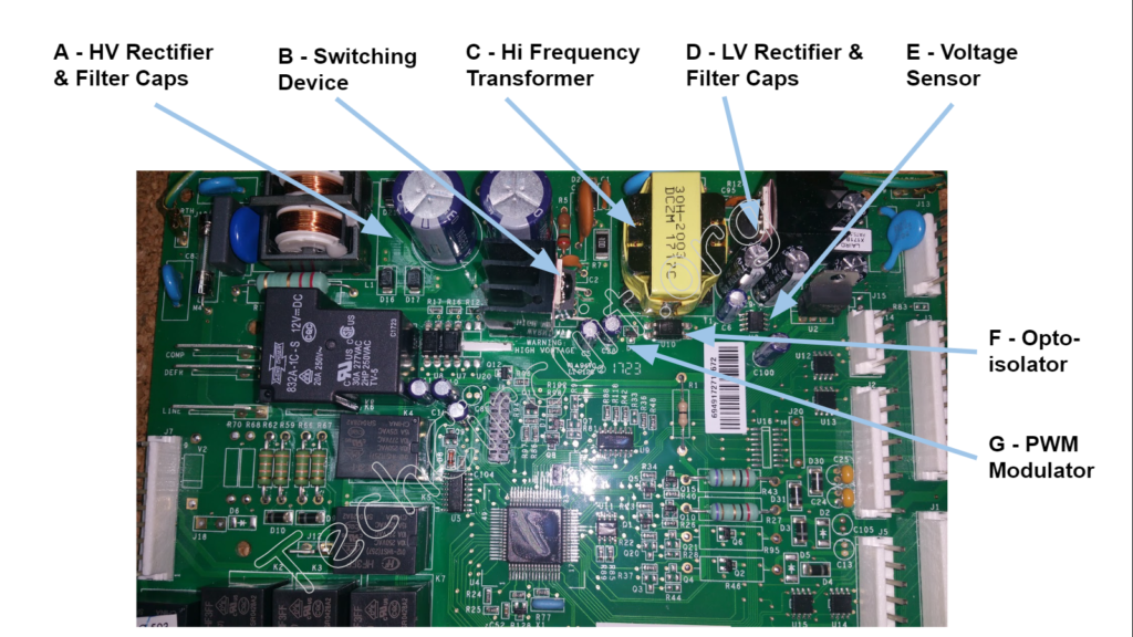
Figure 3 shows an actual switching power supply for a refrigerator control board. The following block diagram describes the corresponding functional blocks.

Figure 4 below shows and describes each block for the example switching power supply.
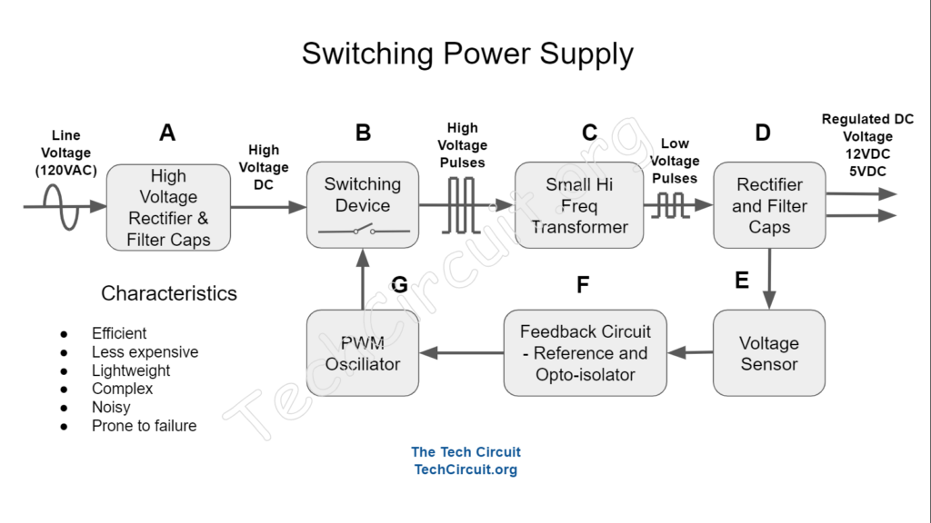
Referring to Figure 4, the example power supply block diagram has an input voltage of 120VAC RMS. The input voltage is processed in a different way than in linear supplies – as follows.
A) The 120VAC RMS (or 170V peak) is immediately rectified and filtered. This results in a relatively high DC voltage of 170V which is stored on high voltage electrolytic capacitors.
B) The 170VDC is then “chopped” by a switching device that creates an oscillating waveform at a relatively high frequency (between 20KHz and 100 KHz).
C) In this block, the oscillating voltage is fed into the small high-frequency transformer that steps the high oscillating voltage down to a much lower level. At such high frequencies, much smaller transformers can be used.
D) Here, the stepped down oscillating voltage is rectified by diodes and filtered by capacitors. 12V will be the main regulated DC output and 5V will be derived from that either by a small linear regulator or another tap on the transformer secondary that is independently rectified and filtered.
E) A voltage sensor detects the current output voltage and reports it to a the feedback circuit.
F) The feedback circuit drives an optoisolator that sends an error signal to the primary side of the circuit to the PWM modulator. The optoisolator is composed of an LED and a photo-transistor so that isolation from the line voltage is maintained.
G) The PWM modulator gets the error signal from the optoisolator so that it knows what pulse width is needed to drive the switching device for regulation. If the output voltage of the SMPS power supply is too high, the PWM pulse width gets narrower to reduce the voltage output, and does the opposite if the voltage gets too low. This regulation cycle occurs at thousands of times per second and is not perceivable at the output of the supply.
Advantages and Disadvantages of a Switching Power Supply
Switching Power Supply Advantages
1. Cheaper – high frequency transformer much smaller and less costly.
2. Light – high frequency transformer is much lighter and require special mounting.
3. Efficient – very little waste heat from transformer and uses PWM regulation to take advantage of full-on and full-off nature of switching device – which dissipates very little power.
Switching Power Supply Disadvantages
1. More complex and difficult to design.
2. Noisy – higher frequency.
3. Less stable and less resistant to voltage spikes – the switching device is easily damaged by voltage spikes because it is already subject to a high voltage during normal use.
4. Higher failure rate of filter capacitors – the electrolytic capacitors are smaller because of the higher frequency – but must handle a similar amount of current as the larger linear supply capacitors. The result is that a similar amount of power dissipation takes place in a much smaller package – resulting in overheating and loss of electrolyte – which increases ESR (Equivalent Series Resistance).
Switching Power Supply Failures and Troubleshooting
Switching supplies are less stable and more prone to failure. Some of the failures modes are:
1. Failed input diodes (Block A) – over voltage or over current conditions can cause these rectifiers to short out. This will typically blow a fuse on the board. The shorted diodes will read close to zero ohms.
2. Shorted or damaged switching device (Block B). This device already runs at a high voltage. Any over voltage condition can easily cause it to fail.
3. Failed and/or dried secondary filter electrolytic capacitors (Block D) . Since switching power supplies operate at a high frequency, these capacitors are very small for the amount of current that flows through them and the power that is consequently dissipated. Their small size means that they cannot dissipate the heat from this power as easily. They run hot and the electrolytic conductor evaporates or boils out. When this happens they develop a high ESR and can no longer filter the supply – resulting in an output voltage drop-out.
I describe Linear and Switching Power Supplies in more detail in this video:
Test your Practical Knowledge of Power Supplies!
Understanding Linear vs. Switching Power Supplies in Appliances
Select the best answer for each question.
Disclaimer
This blog is intended for experienced or supervised technicians. Always take appropriate safety precautions when dealing with live circuits. For informational purposes only. Utilize the concepts in this blog at your own risk. The Tech Circuit or Steve Morrison assumes no responsibility or liability for any errors or emissions in the content of this blog. The information contained in this blog is provided on an as is basis with no guarantees of completeness, accuracy, usefulness, or timeliness. Never attempt to repair circuit boards in appliances or HVAC systems unless you are directly supervised by a licensed professional engineer and doing so under approved ISO and UL processes.
Don’t forget:
“Diverting 10 min/day of social media time towards learning something new, is 5 hours of newfound monthly knowledge.” – SM
To DONATE to the Tech Circuit – CLICK HERE
Alphabetical Links to all Tech Circuit Articles and Blogs – CLICK HERE
Links to all Tech Circuit Cheat Sheets/Field References for Appliance/HVAC Techs – CLICK HERE
For additional electrical and electronics learning material for field techs, visit our homepage at http://www.TechCircuit.org or our Facebook group at https://www.facebook.com/groups/746823709133603.
We are a participant in the Amazon Services LLC Associates Program, an affiliate advertising program designed to provide a means for us to earn fees by linking to Amazon.com and affiliated sites.