How to Test Diodes, Transistors, Triacs, MOSFETs and IGBTs with a Multimeter
This page shows how to use a multimeter to test the most common semiconductors (diodes, transistors, etc), along with their associated readings and values. Readings outside of these ranges indicate likely failed components.
Diodes, transistors, and other types of semiconductors are based on the “PN” junction, which allows current to flow one way but not the other. One trade-off of this feature is that when current does flow there is a voltage drop across that junction (usually around 0.7v). This is called the “forward biased” condition. When the diode (or junction) is “reverse biased” no current flows (unless the maximum reverse voltage drop rating is exceeded). The latter is an unusual case that need not frequently be considered unless you are actually designing circuits.
Semiconductors most often short when they fail. When this happens, you will read close to zero ohms instead of the proper readings shown herein. Sometimes semiconductors partially short out – which results in what’s known as a “leaky” condition. When this happens, you can get a resistance reading with an ohmmeter – which is usually not seen with a healthy semiconductor. More semiconductors will be added as needed.
*CLICK HERE TO DONATE TO THE TECH CIRCUIT*
Semiconductor Testing by Type
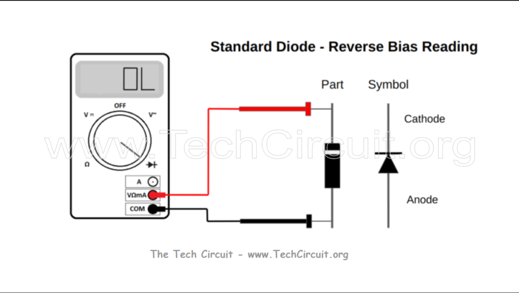
Standard Diodes
Standard diodes (not zener or Schottky diodes) will have a forward voltage drop of between 0.6 and 0.7 volts when measured with the diode check mode. The reverse voltage drop should read out of range or “OL”. Some specialized diodes such as the Schottky type will have a much lower forward voltage drop (around 0.2v). These are often found in high-speed switching (SMPS) type power supplies on control boards. Note that this test is not appropriate for microwave diodes since they typically have a forward voltage drop of greater than 5 volts.

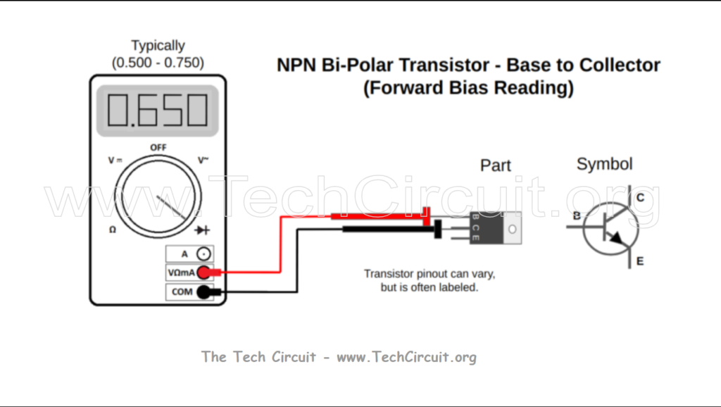
Transistors
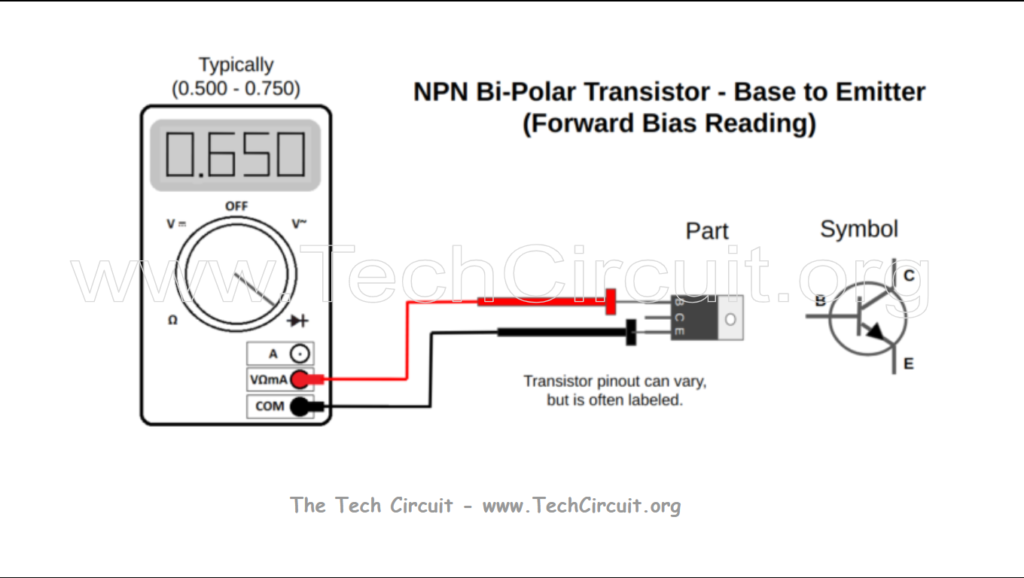
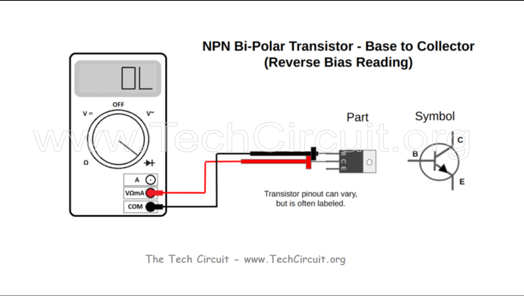
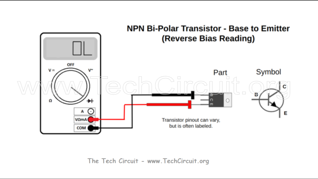
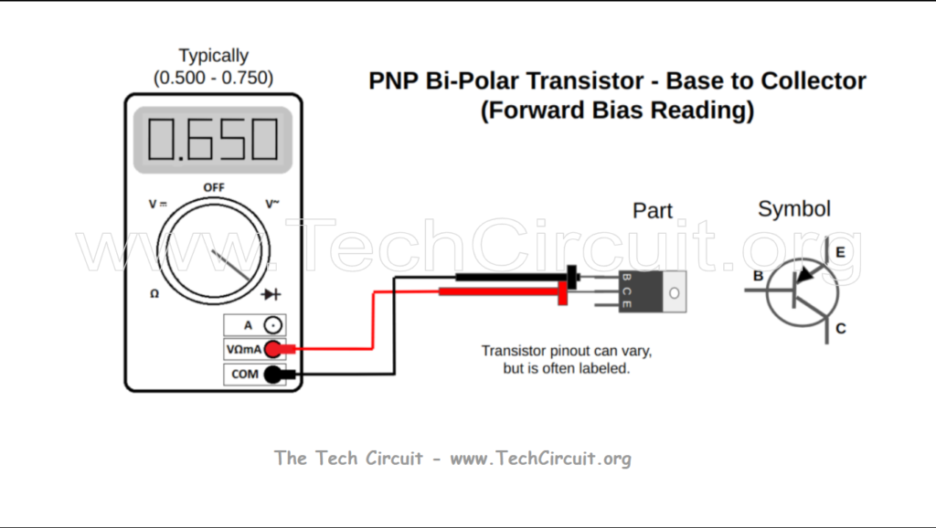
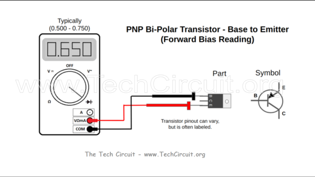
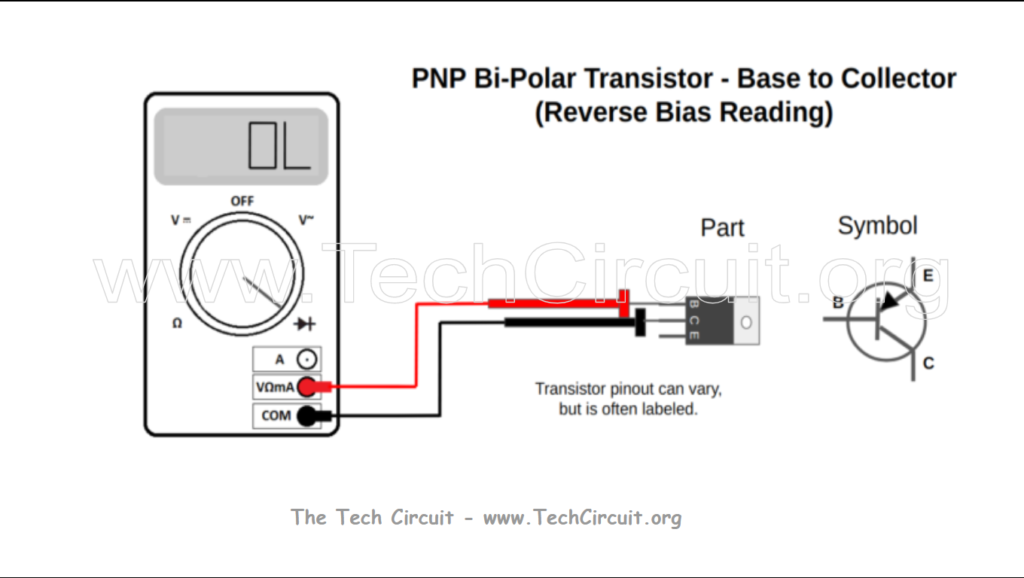
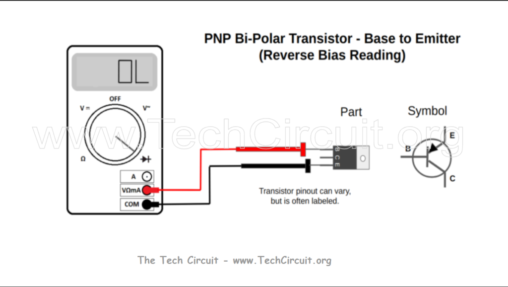
Bipolar transistors will often be labeled with some combination of E,B, and C for Emitter, Base, and Collector. Two primary types exist: NPN and PNP, depending on their application in a circuit. When testing bipolar transistors, you will be measuring forward and reversed biased junctions just like with standard diodes as shown in the diagrams.
Common Transistor Pinouts
Below are pictures of typical pinouts for common transistor package types, although there are some variations of these.
To-220 Package
TO-92 Package
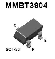
SOT-23 Package
NPN Transistor Testing
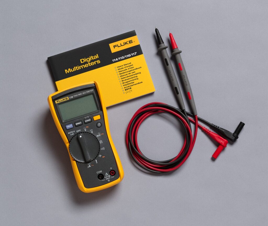
Click Below to Purchase the Fluke Multimeter
PNP Transistor Testing
Click Below to Purchase the Klein Multimeter

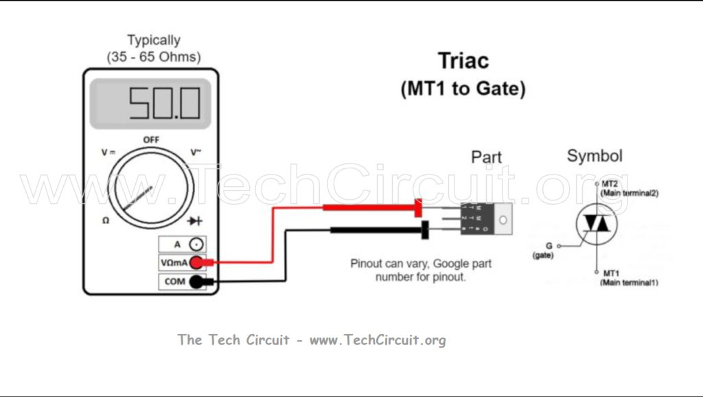
Triacs
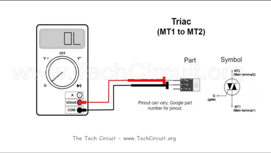
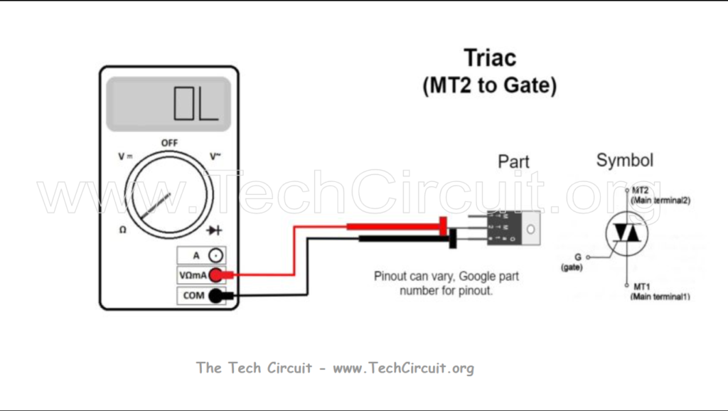
A Triac is used to meter AC current, instead of DC current like it’s Bipolar Transistor counterpart. The best way to test a triac is by using a dedicated test-circuit. However, most triacs that technicians encounter (ones that act as solid-state AC relays and dimmers for 120V circuits) have characteristic resistance readings. Below are common readings for good triacs. Failed triacs often appear burnt, cracked, or otherwise visibly damaged. When measured, they usually are internally shorted, with low-ohm readings between MT1 & MT2 or between either of these terminals and the GATE.
The following triacs are tested using the resistance setting on a multimeter. Polarity isn’t relevant because you aren’t using diode check mode and don’t have enough test voltage to forward bias the junctions.
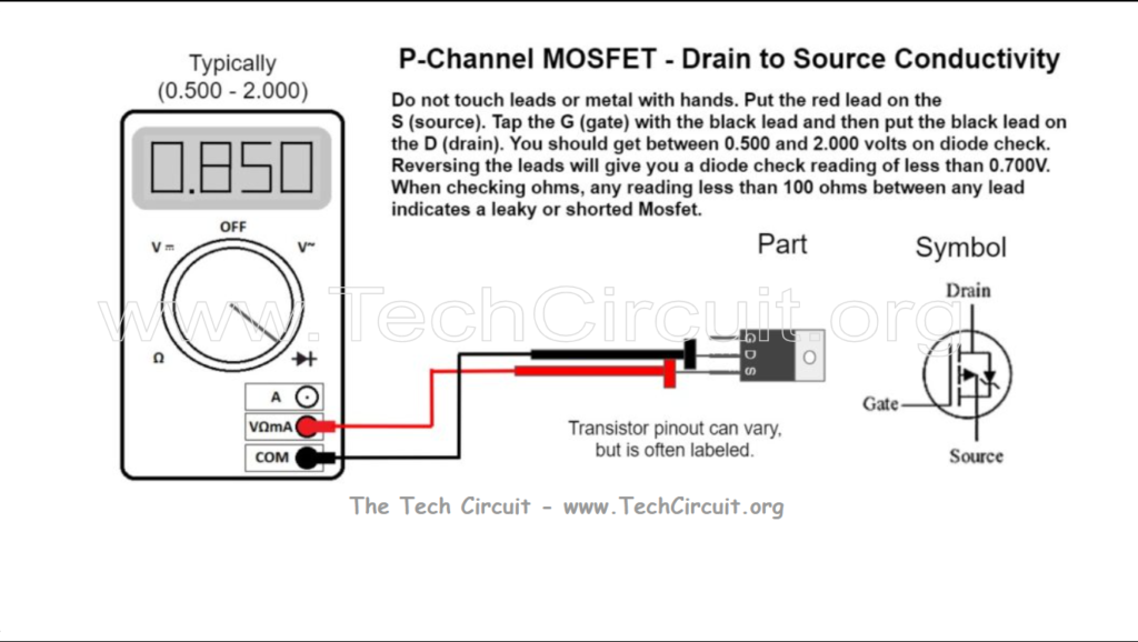
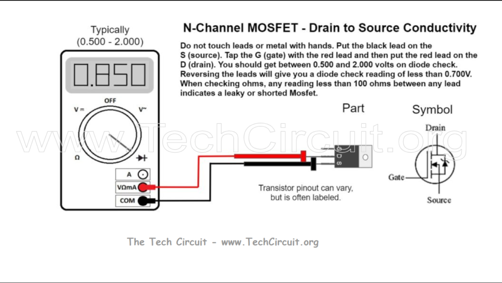
MOSFETS
Like Bipolar Transistors, Mosfets are typically used with DC current, but have very different behavioral characteristics. As well, instead of an Emitter, Base and Collector, the Mosfet has a Source, Gate and a Drain. They come in P-channel and N-channel types. They are commonly failing devices in switching power supplies and inverters. When they fail, they most often do so catastrophically – and will be noticeably burnt and/or cracked. This is because they frequently switch high voltages and currents. When they fail in this way, you will usually read a short (or low resistance) between two or more of the leads – and can simply be tested in-circuit. They can fail in other ways too. If not shorted, the Mosfet will need to be removed from the circuit for definitive testing. They are so sensitive that anything connected to them will interfere when trying to test them. The next two images are guides for how to test commonly found power Mosfets. Follow the guide thoroughly and step-by-step in order to get the correct result. You will need to first determine if the Mosfet is a P-channel or N-channel Mosfet. The easiest way is to get the part number and google it. By the way, P-channel Mosfets are often found with the source (S) lead connected to the + supply voltage in a circuit, whereas N-channel ones are often found with the source (S) connected to ground. That orientation may help you determine which type of Mosfet you are testing.
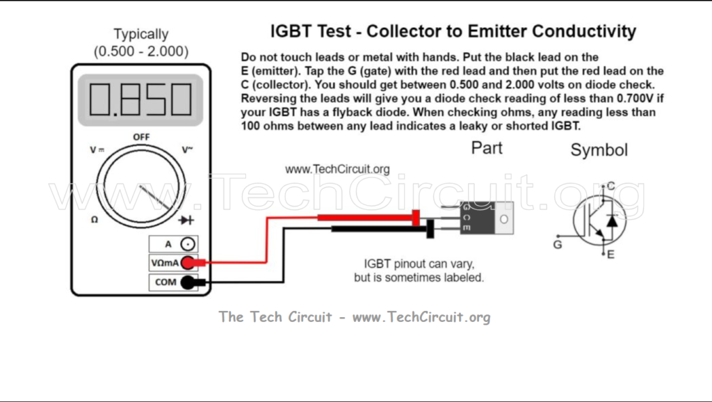
IGBTs
The IGBT or Insulated Gate Bipolar Transistor, is kind of a hybrid between a MOSFET and an NPN BJT (bipolar junction transistor). It has an emitter, gate, and collector pin. It benefits from the relatively fixed voltage drop from collector to emitter like that of a BJT and the high gate input impedance of an FET. The fixed voltage drop (usually 2 volts or less) enables it to handle very high currents while dissipating very little heat as compared to MOSFETS – that have voltage-drops that depend on their on-resistance. The operational voltage-drop across the device, by the way, is key in determining how much heat the device has to dissipate – which is why the relatively low voltage-drop of the IGBT’s makes them so attractive for high-current applications.
Since IGBTs handle such high currents (and voltages) however, they frequently fail catastrophically. Their failure is often physically obvious or indicated by a short circuit between the gate and emitter or collector and emitter. There is a way to test an IGBT’s conductivity as shown in the following image. Note that IGBT’s are often connected to motor windings, transformers, and other low impedance/resistance loads. As such, it is best to remove them for an actual conductivity test.
Don’t forget:
“Diverting 10 min/day of social media time towards learning something new, is 5 hours of newfound monthly knowledge.” – SM
To DONATE to the Tech Circuit – CLICK HERE
Alphabetical Links to all Tech Circuit Articles and Blogs – CLICK HERE
Links to all Tech Circuit Cheat Sheets/Field References for Appliance/HVAC Techs – CLICK HERE
For additional electrical and electronics learning material for field techs, visit our homepage at http://www.TechCircuit.org or our Facebook group at https://www.facebook.com/groups/746823709133603.
We are a participant in the Amazon Services LLC Associates Program, an affiliate advertising program designed to provide a means for us to earn fees by linking to Amazon.com and affiliated sites.
One thought on “Semiconductor Testing Cheat Sheet™”