Basic Electricity Course and Quiz for Appliance Technicians
NOTE: This basic electricity course, the associated video and derived videos are all FREE. It is all part of our mission to better empower Appliance Technicians by enhancing their electrical skills. Developing this content takes many hours though. You can show your support for this mission by *DONATING HERE*
*SEE THE VIDEO VERSION OF THE COURSE HERE*
It is important to understand electricity basics when servicing appliances. After all, you will need to electrically troubleshoot them sooner than later. You don’t want to be the Technician that encounters a simple electrical problem and is unable to complete their diagnosis. If you have even a basic understanding of how Voltage, Current, and Resistance behave in a circuit, as well as the main differences between 240v and 120v appliance circuits, you’ll be a more effective at your job and will provide better value to your customer.
What is Voltage and Current?
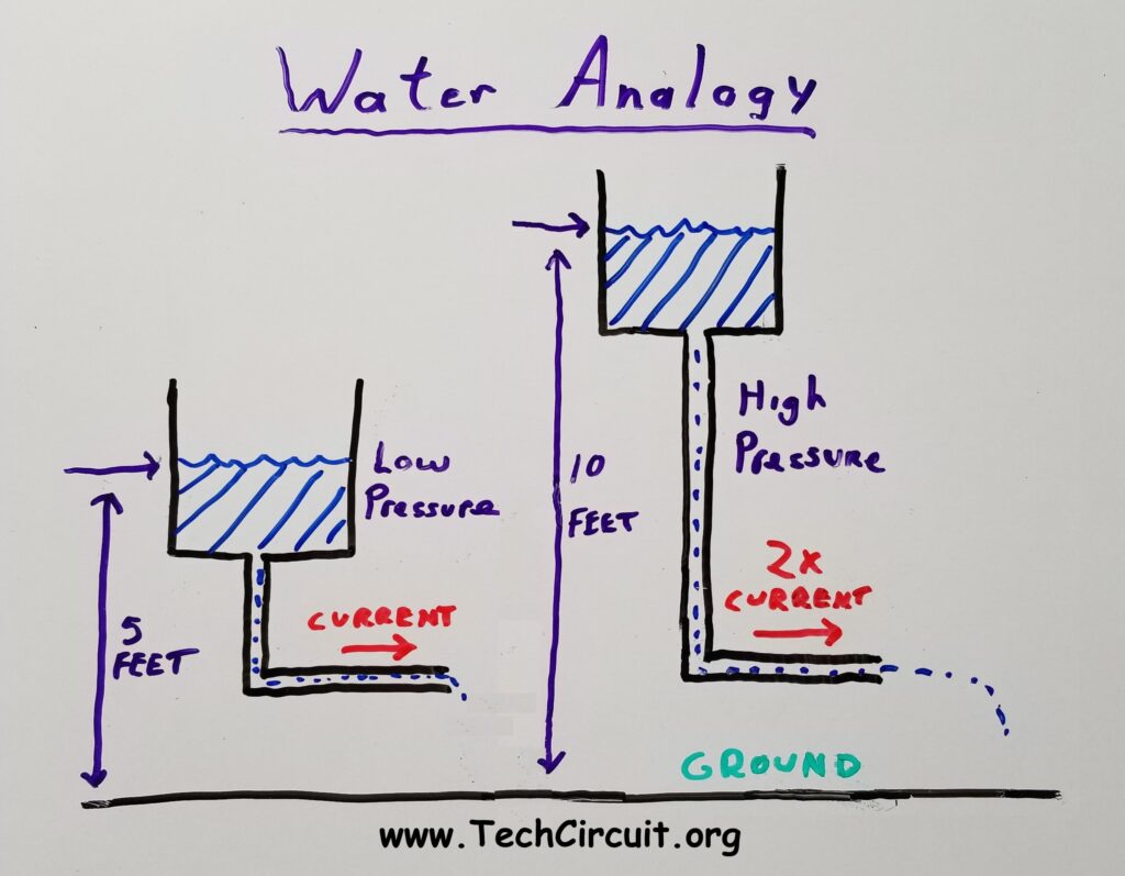
Voltage is the force, or pressure that pushes current through a conductor, like a wire. It is always measured as a difference between two points. Without voltage, there would be no current. Current is the rate of flow of electrons that are being pushed through a conductor (like a wire) by the force of voltage. You’ve seen the simple water analogies. From a conceptual standpoint, they are useful in helping understand how voltage and current work. In the image below, you have two water tanks with pipes that release the water. The tank on the left is 5 feet off of the ground. The one on the right is at a height of 10 feet. The higher water tank puts more pressure on the water column because of the additional weight of that column. This is analogous to a higher voltage level above ground potential. Thus the water flows through that pipe at a higher rate than the 5 foot tank on the left side – as shown by how how much further the water is ejected from the pipe on the right. The higher pressure is analogous to higher voltage. The faster rate of water flow is analogous to more current flow.
Be sure to subscribe to our Youtube Channel!
For tons of videos on electrical and electronics diagnostics, practical electrical theory, and field-technician resources, click the picture below or this link here: https://www.youtube.com/@TheTechCircuit?sub_confirmation=1

Water Analogy of a Load
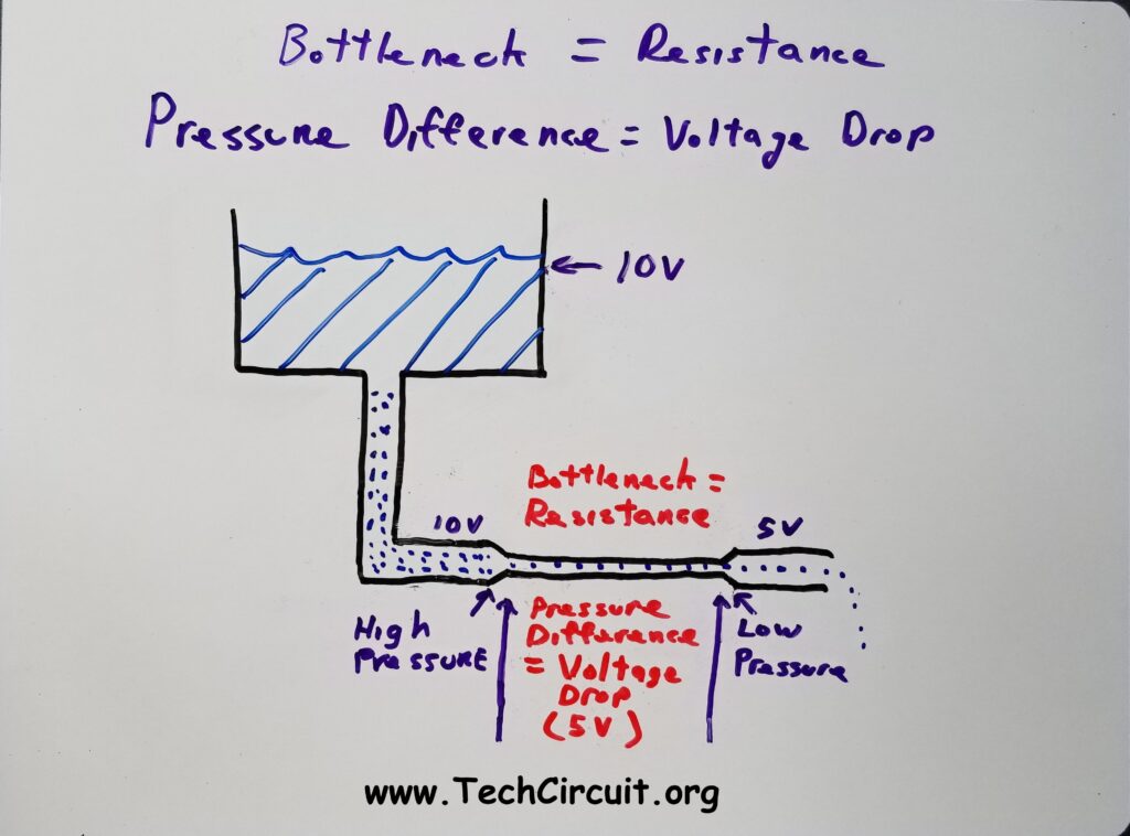
All electric circuits have loads. Loads do work by producing heat, motion, or performing other functions. The simplest type of load is a resistor, such as a heating element. Whenever current passes through a resistor, a voltage appears across it. That resistor is analogous to a bottleneck in the water pipe as shown below. The bottleneck impedes the water flow and causes the pressure difference between the left and right sides of the bottleneck. This pressure difference is analogous to a voltage drop across a resistor.
Electrical Equivalent of Water Analogy
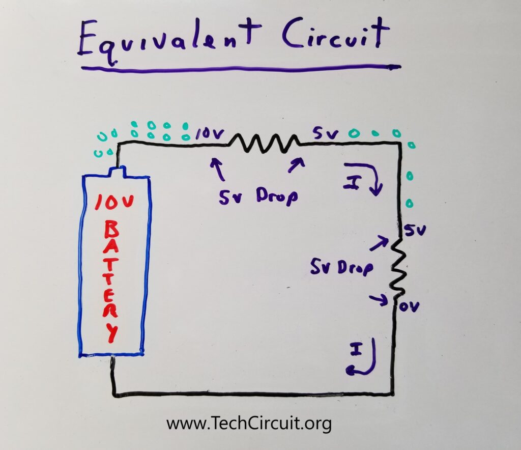
Below is the electrical equivalent of the above water analogy. The resistor takes the place of the bottleneck. The pressure difference is now a voltage difference. Based on the voltage difference, the voltage drop across the resistor is 5v. The green dots represent the electrical charge. As it encounters resistance, that charge backs up on the left side of the resistor. Much like the water backing up on the left side of the bottleneck. Notice that we have added an additional bottleneck (resistor), since the total voltage dropped across the resistors must be equal to the supply voltage.
Voltage, Current, and Resistance are Predictable
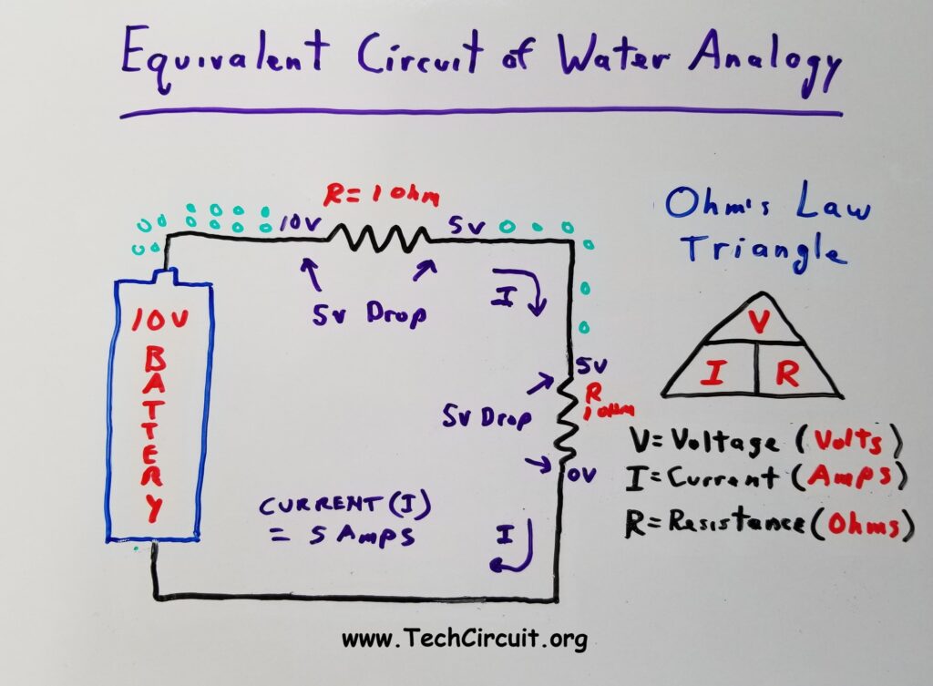
A simple formula based on the Ohm’s Law triangle gives you the predictable relationship between Voltage, Current, and Resistance. The image below takes the above equivalent circuit a step further by using the Ohm’s Law triangle to determine the current through the circuit. Using Ohm’s Law, if each resistor is one ohm, the total circuit resistance is 2 ohms. You can now calculate the current through the circuit.
Using the triangle the current I=V/R. So you have 10V/2ohms = 5 amps. Simple enough. Note that this current is the same through the entire circuit. That’s how current works. You can now find the voltage drop across each load (resistor). Voltage = I x R. So each resistor has (5 amps) x (1 ohm) or 5 volts across it. Note also that the total of all the voltage drops equals the supply voltage (the battery). Again, that’s how voltage works.
Power (Wattage)
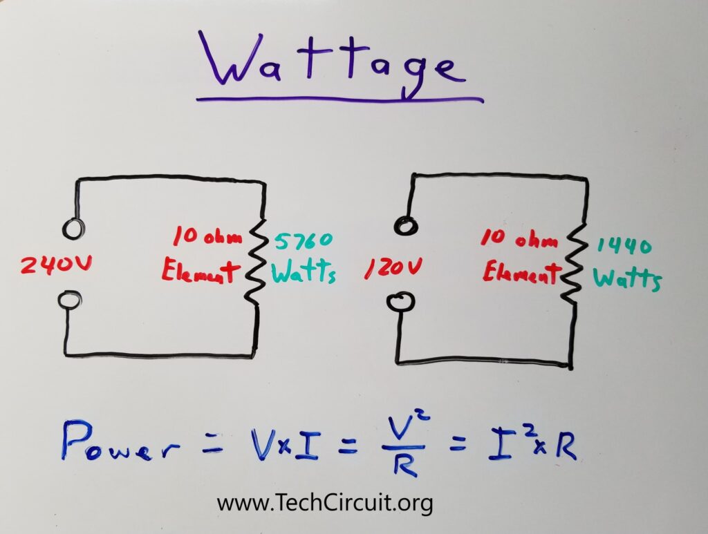
Power is the rate of work that is being performed in a certain amount of time. That work is based on transferring energy to a load (like a heating element or motor). The more energy that is transferred to (or used by) a load per second, the higher the power (in watts) of that transfer or use.
Wattage is very easy to determine. Looking at the diagram below. We can see that the power dissipated by a 10 ohm dryer element with 240 volts across it is 5760 watts. Wattage is a bit non-intuitive though. If you reduce the voltage across that dryer element to 120 volts, the power is only 1/4 of what it was before, or 1440 watts. This is because fundamentally, power is equal to voltage time current. But if you drop the voltage in half, you also drop the current in half (per ohm’s law). You can also see this exponential difference in heat output by using one of the other formulas for power: P = V²/R. So if you have a dryer or range element that only has 120 volts across it (because of an incorrectly installed cord for example) the element will only dissipate 1/4 of the wattage and may only seem warm, as opposed to hot. The image below schematically describes this phenomenon.
Appliance Voltages and Configurations
240v Appliances
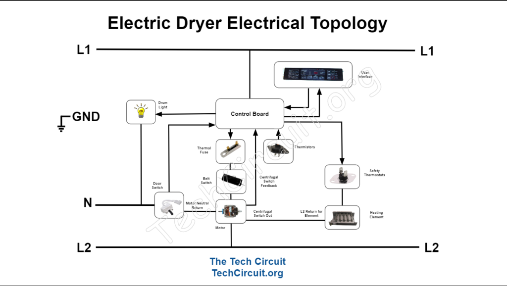
In the United States, most 240 volt appliances adhere to a common arrangement in they way they power loads and controls. 240 volts is advantageous for electric heating, because as you read previously, elements can dissipate four times the heat as with 120 volts. Below shows the typical way that both an electric dryer and a range are configured. The dryer primarily contains two 120 volt circuits and one 240 volt circuit: The main control and motor are both 120 volt circuits, the latter of which, is activated by a relay on the main control. The heating element is the 240 volt circuit that is also activated by a relay on the main control. Finally, a centrifugal switch inside the motor must be closed in order for the element to be energized.
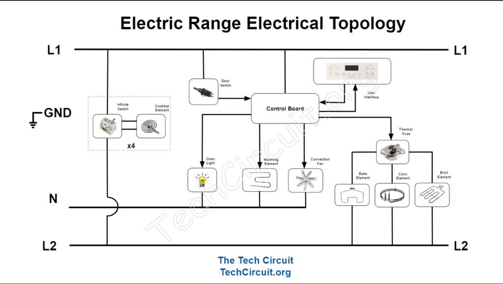
The range consists of a control board that is supplied 120v from L1 to Neutral. Within that board, are relays that complete the circuit between L1 and L2 for the Bake and Broil elements. Those relays isolate the 120v L1-N board circuit from the 240v L1-L2 Bake/Broil circuit. Also part of the 240v circuit, are typically 4 burners controlled by infinite switches. These switches vary the amount of time that voltage is supplied to each burner.
120v Appliances
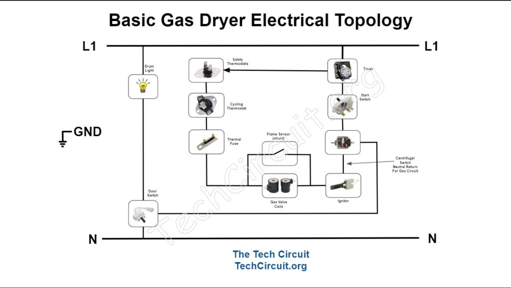
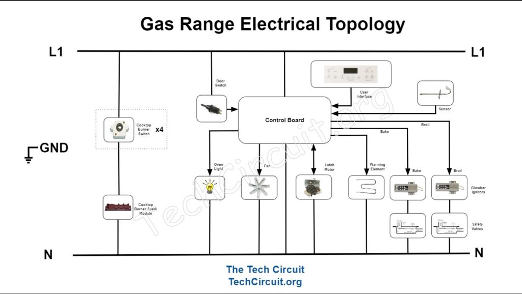
Most gas ranges and dryers utilize 120 volts. Heat for cooking and drying is produced by gas combustion. Thus there is no need for a 240 volt supply in most cases. Below are a few (simplified) electrical configurations for gas appliances. The gas dryer consists primarily of three 120 volt circuits: The main control, the motor, and the gas ignition/valve circuit. The motor and gas circuit are each activated by the timer or relays on the main control. There is a radiant sensor that pulls current through the ignitor before ignition, but opens up to allow current to flow through the gas circuit after ignition. In this case, the radiant sensor acts as a current “shunt” until it opens and allows that current to be diverted through the gas coils. The gas circuit also relies on a centrifugal switch inside the motor in order to be energized. This is a safety feature that increases the chance that the blower will be pulling the flame through the funnel.
The gas range consists of four primary circuits: The main control, the bake circuit, the broil circuit, and the spark module. The bake circuit consists of a gas valve in series with an NTC (negative temperature coefficient) ignitor, which decreases in resistance as it gets hot. As it decreases in resistance, the current in the circuit naturally increases. When it gets hot enough, the current through the series circuit is enough to open the valve and allow combustion to occur.
The spark module has four sub-circuits, which are the switches behind each knob that activates its respective cooktop burner. Note that no matter what knob is turned, all burners will “spark”.
Troubleshooting 240v Appliances
PLEASE NOTE THAT THE FOLLOWING INFORMATION INVOLVES DIAGNOSING LIVE EQUIPMENT THAT THAT MAY RESULT IN ELECTRIC SHOCK. IT IS ONLY INTENDED FOR QUALIFIED TECHNICIANS OR THOSE UNDER THE SUPERVISION OF QUALIFIED TECHNICIANS AND DONE SO AT YOUR OWN DISCRETION AND RISK.
Diagnosing 240 volt circuits is easiest when you avoid referencing ground or neutral in your measurements. This is because the circuit that involves the load (element) gets its voltage from the difference between L1 and L2, which is 240 volts. In that part of the circuit, neutral is not the return path. L1 or L2 are, depending on which side of the circuit you’re on. Also, L1 and L2 are of opposite polarity. If you lose L1 at the plug or terminal block, and you use Neutral as a test reference, L2 may travel through an element or another component. When you try to measure L1 with respect to Neutral, you may be mistakenly measuring L2.
Suppose you have a range that won’t broil. Thus the best way to troubleshoot 240 volt circuits is to measure L1 or L2 with respect to one another. Suppose you have 240 volts getting to the range terminal block, and the element ohms out (is good). What do you do now? There is apparently an “open circuit” in the path that contains the load. The diagram below illustrates how you can identify this open circuit by referencing L1 on the terminal block. Here are the general steps after doing the basics – checking for voltage at the range and ohming out the element – by using a “point-to point voltage drop test”:
- Identify your Target Load (the broil element).
- Set your multimeter on AC volts.
- Connect one lead to L1 using an alligator clip.
- Turn on the broil function.
- Trace step by step through the circuit from L1 towards L2 (the return path), watching the voltage, good components, except your target load, should real close to zero volts.
- Once you read 240 volts, the component just prior to your test lead is suspect.
- Sometimes you may read a voltage between 0 and 240 volts. This usually means a a loose connection that is allowing some voltage to still get to the element, but not enough for it to become hot.
240v Point-to-Point Voltage Drop Test Example
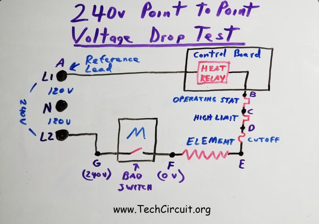
Referring to the image below – you arrive to a customer’s house with a 240v electric dryer “no heat” complaint. You do the basics. You’ve tested for 240v at the terminal block from L1 to L2 using your LowZ meter. You then open the dryer and test the element, thermal cutoff, high limit thermostat, and operating thermostat). They all test good (Element is about 10 ohms. The cutoff, high-limit thermostat, and operating thermostat are all approximately zero ohms). You now suspect either the heat relay or motor’s centrifugal switch. How can you be sure though?
You are about to find out that the motor has a bad centrifugal switch. Using the step by step point-to-point method as described above, you set your meter for AC voltage and connect your reference lead to L1 as shown in the image below. You start the dryer in heat mode. You then, (step-by-step), check the voltage at each point, starting with point B. Why? Because voltage drops favor the highest resistance. If you see 240 volts at point B, you know that the relay contacts are open (infinity resistance), but it reads 0 volts – which means the relay contacts are closed (like a switch). You go down the line to points C, D, E, and even F, but still read 0 volts. Finally, you check point G. You get 240 volts. Why? Because the centrifugal switch is open, and is the highest resistance (infinity) in the circuit.
To remedy this, you replace the motor. Now point F has 240 volts with respect to your L1 reference point. That means the motor now has 0 volts across the centrifugal switch. As it should be. The element is now the highest resistance component in the circuit because it is 10 ohms and everything else along the line has a resistance of zero ohms. So 240 volts now appears across the element.
It may be important to note that if you have a “no-bake” symptom with an electric range, you may have a bad relay. The voltage to the relay coil is derived from a 120 volt circuit. However, when determining that the relay contacts weren’t making contact, you are still in the 240 volt circuit. To determine why the relay didn’t even energize or “try” to close the contacts, you are in the 120 volt circuit because the voltage that triggers the relay is derived from that circuit.
Troubleshooting 120v Appliances
Troubleshooting 120 volt appliances can be done much in the same way (above) as with 240 volt appliances. However, your return path is neutral – in which case it is OK to reference neutral. In fact, you can use a voltage pen for quick location of open circuits. Note that 240 volt dryers normally use 120 volt motors. When troubleshooting such a circuit, you can use Neutral as your reference, even though the appliance is plugged into a 240 volt outlet. Also remember, there is rarely a reason to reference ground, unless you are looking for problems with the actual ground connection between the appliance and the breaker box , floating/loose neutral, or testing for a grounded component. There should be 0 volts voltage between ground and neutral when they are both properly connected in the breaker box. This is true of both 240 volt and 120 volt appliances. Ground is never intended to carry current on a regular basis.
240v Power Cord Connections
For 240v appliances that plug into a receptacle, are 2 types of cords typically used. One is old-style 3-wire cord and the other is a relatively newer-style 4-wire cord.
The 3-wire Cord
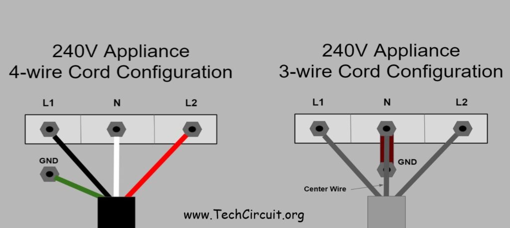
The older-style 3-wire cord consists of L1, L2, and Neutral. The voltage difference between L1 and L2 is 240v for most residential homes in the United States. The voltage difference between L1 and Neutral, as well as L2 and Neutral is 120 volts respectively. The Neutral wire is normally the return path for L1 and is also bonded to the chassis (metal enclosure) of the appliance by a copper strap connected to the center lug of the terminal block. It is supposed to have an electrical potential of 0 volts as compared to Earth ground.
The 4-wire Cord
The newer 4-wire style cord adds a ground wire. The ground wire is intended to be bonded to the chassis (metal enclosure) of the appliance. The voltage difference between L1 and L2 is the same as with the 3-wire cord. Also, just like with the 3-wire cord, the voltage difference between L1 and Neutral, as well as L2 and Neutral is 120 volts respectively. The Neutral wire is still the return path for L1 and has a 0 volt potential difference from Earth ground. The main thing that distinguishes the 4-wire cord from a 3-wire cord is that Neutral is NOT bonded to the appliance chassis (metal enclosure). This is intentional. It is an added safety feature that minimizes the chance that the chassis will become energized. The Ground wire is the only wire that is to be connected to the chassis with a 4-wire cord. Below is an image of the correct way to connect both 4-wire and 3-wire cords.
Incorrect 4-Wire Power Cord Connections
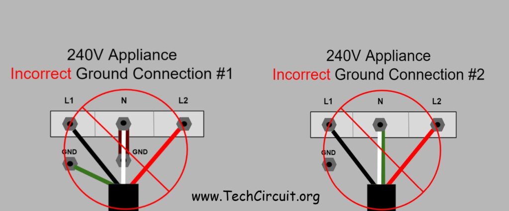
Connecting Neutral to the chassis with a 4-wire cord is against code and is unsafe. Also, connecting both ground and Neutral together at the center terminal on the terminal block is against code (whether you leave the copper grounding strap in place or not). Ground and Neutral are intended to be part of separate circuits. In other words, ground is not intended to carry current on a regular basis. It is only there to provide an emergency return path to the breaker box in the event of a short circuit to ground. Note that Ground and Neutral are bonded together inside the breaker box. This does not mean that it is appropriate to bond them together beyond that. It may be non-intuitive to Technicians, but there are specific electrical reasons for this that are safety related. Please refer to the images below of two types of incorrect 4-wire power cord connections that should be avoided or corrected if encountered in the field.
Electrical Troubleshooting Equipment
Some useful tools for electrical troubleshooting are:
A clamp-meter with LowZ, temperature, capacitance, frequency, diode check, and non-contact voltage testing (like a voltage pen).


Click Here for a suggested product that meets all of these requirements.
Click Here for the Klein CL390
A voltage pen for testing the presence of AC voltage above the ground potential.


Click Here for a suggested product.
Quiz (answers at the end)
Let’s see how much you learned by taking this comprehensive quiz (answers at the end):
- What is Voltage?
- It is the rate of flow of electrons through a wire.
- It is the power that energizes a load
- It is the force that causes current to flow through a conductor.
- It is what resists the flow of electricity.
- What is current?
- It is the force that causes current to flow through a wire.
- It is what resists the flow of electricity.
- It is the rate of flow of electrons through a conductor.
- It is the power that energizes a load
- What is true of Voltage and Current?
- Voltage passes through and current is just there.
- Voltage is a potential difference between two points that causes current to flow.
- Voltage flows as a result of the difference of current between two points.
- Voltage and current are not related.
- What does the height of the water in the water analogy represent?
- Current
- Resistance
- The voltage level with respect to ground
- A voltage drop
- What does the rate of flow of water in the water analogy represent?
- Voltage potential
- Current
- Resistance
- A bottleneck
- What does the bottleneck in the pipe in the water analogy represent?
- Resistance
- Power
- Pressure
- Current
- What does the pressure difference from one side of the bottleneck to the other in the water analogy represent?
- Resistance
- Power
- Current flow
- A voltage drop
- In a circuit with only one branch as shown in this article, how does current behave?
- Current decreases as it reaches the return path.
- Current remains the same through the entire circuit.
- Current increases through resistors.
- Current drops across each resistor.
- In a series circuit with more than one resistor, how does voltage behave?
- The voltage across each resistor is equal to the supply voltage.
- The sum of the voltages across each resistor adds up to the supply voltage.
- The voltage across each resistor is not related to the supply voltage.
- All of the above.
- If you have 240 volts across a 10 ohm element, how much current flows through that resistor?
- 2400 amps
- 24 amps
- 12 amps
- None of the above
- What is wattage?
- It is related to the rate of heat dissipated by a resistor when current flows through it.
- It is the rate of work done by a load.
- It can be calculated by V x I.
- All of the above.
- If a 10 ohm element has 120 volts across it, it dissipates 1440 watts of heat. If you double the voltage across the element, how many watts does it now dissipate?
- 2880 watts
- 720 watts
- 5760 watts
- 0 watts
- What is the best reference to connect one lead of your voltmeter to when using the “Voltage Drop Method” on a 240 volt dryer element circuit?
- Neutral
- Ground
- L1 or L2
- None of the above
- Why is it best to avoid referencing Neutral or Ground when troubleshooting a failure in a 240 volt circuit (such as a no-bake)?
- Neutral and Ground are not part of the 240 volt bake circuit.
- You can be trying to measure L1 and actually be reading L2 that is passing through a component in the circuit.
- None of the Above
- All of the Above
- What is the best reference to connect one lead of your voltmeter to when using the “Voltage Drop Method” on a 120 volt gas range when checking the gas valve/ignitor circuit?
- L2
- L1
- Ground
- Neutral
- If you have a 240 volt dryer but want to use the voltage drop method to check the motor circuit, what is the best terminal to reference at the block?
- L2
- L1
- Ground
- Neutral
- What is one of the few instances when ground should be used as a reference in troubleshooting appliances?
- Never
- When a dryer produces no heat
- When checking for a floating neutral
- When a motor won’t start
- Why should ground and neutral be electrically separated at the terminal block with a 4-wire cord?
- Because they are intended to be part of separate circuits.
- Because ground should not carry current on a regular basis.
- Because it is minimizes the chance that the enclosure will become energized.
- All of the above.
Quiz Answers
- What is Voltage? Answer: It is the force that causes current to flow through a wire.
- What is Current? Answer: It is the rate of flow of electrons through a wire.
- What is true of Voltage and Current? Answer: Voltage is a potential difference between two points that causes current to flow.
- What does the height of the water in the water analogy represent? Answer: The Voltage level with respect to ground.
- What does the rate of flow of water in the water analogy represent? Answer: Current
- What does the bottleneck in the pipe in the water analogy represent? Answer: Resistance
- What does the pressure difference from one side of he bottleneck to the other in the water analogy represent? Answer: A voltage drop
- In a circuit with only one branch as shown in this article, how does current behave? Answer: Current remains the same through the entire circuit.
- In a single circuit with more than one resistor, how does voltage behave? Answer: The sum of the voltages across each resistor adds up to the supply voltage.
- If you have 240 volts across a 10 ohm element, how much current flows through that element? Answer: 24 amps
- What is wattage? Answer: All of the above.
- If a 10 ohm element has 120 volts across it, it dissipates 1440 watts of heat. If you double the voltage across the resistor, how many watts does it now dissipate? Answer: 5760 watts.
- What is the best reference to connect one lead of your voltmeter to when using the “Voltage Drop Method” on a 240 volt dryer element circuit? Answer: L1 or L2
- Why is it best to avoid referencing Neutral or Ground when troubleshooting a failure in a 240 volt circuit (such as a no-bake)? Answer: All of the Above
- What is the best reference to connect one lead of your voltmeter to when using the “Voltage Drop Method” on a 120 volt gas range when checking the gas valve/ignitor circuit? Answer: Neutral
- If you have a 240 volt dryer but want to use the voltage drop method to check the motor circuit, what is the best terminal to reference at the block? Answer: Neutral
- What is one of the few instances when ground should be used as a reference in troubleshooting appliances? Answer: When checking for a floating/loose neutral
- Why should ground and neutral be electrically separated at the terminal block with a 4-wire cord? Answer: All of the above.
Please see our “Tech Circuit” video on this subject:
Alphabetical Links to all Tech Circuit Articles and Blogs – CLICK HERE
Alphabetical Links to all Tech Circuit Cheat Sheets/Field References for Appliance/HVAC Techs – CLICK HERE
To DONATE to the Tech Circuit – CLICK HERE
For additional electrical and electronics learning material for field techs, visit our homepage at http://www.TechCircuit.org or our Facebook group at https://www.facebook.com/groups/746823709133603.
TC
We are a participant in the Amazon Services LLC Associates Program, an affiliate advertising program designed to provide a means for us to earn fees by linking to Amazon.com and affiliated sites.
We are a participant in the Commission Junction Affiliate Program, an affiliate advertising program designed to provide means for us to earn fees by clicking on associated links.