This article explains the usage, describes the operational theory, and provides a through review of the Klein CL800 multimeter. You will learn how to use this meter, understand the theory behind the functions, and see how these functions compare to their claimed specifications. The theory behind each function, when noted, will be shown in bold italics, for ease in identification.
About the CL800 Clamp Multimeter
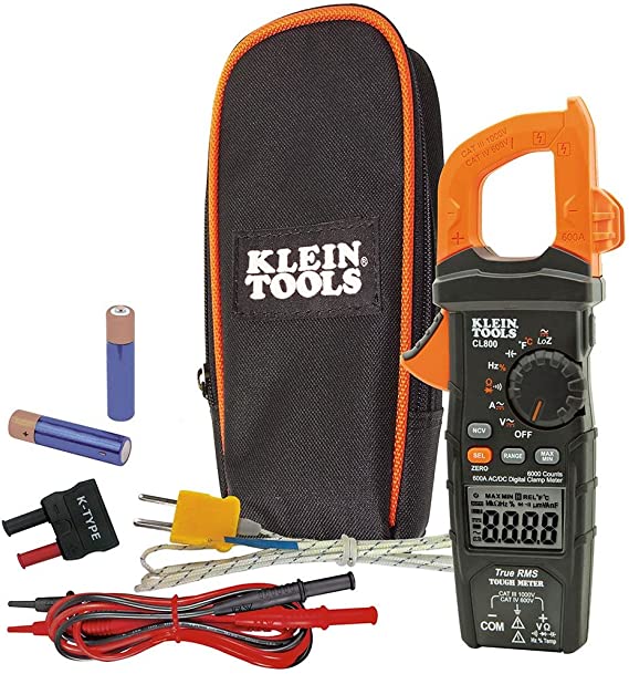
The Klein CL800 was designed for the field technician in mind. It’s features are many, and relevant to the needs of Appliance, HVAC, and other field technicians. In fact, current users of this meter may learn about some features they never knew existed. Here’s a list of those features:
- DC/AC voltage to 1000V (standard mode)
- DC/AC voltage to 600V (LoZ mode)
- True RMS
- Safety Rating – CAT IV 600V, CAT III 1000V, Class 2, Double Insulation
- LoZ (low impedance) voltage measurement
- AC/DC amperage to 600A (using clamp meter)
- Resistance
- Continuity
- Capacitance
- Frequency
- PWM (pulse width modulation) %
- Diode and Semiconductor Test
- Temperature
- Contactless Voltage Detection
- Backlight and Work Light
- Test Lead Holder for Natural Two Handed Operation
I will go through each of these features while describing their theory of operation (shown in bold italics).

Be sure to subscribe to our Youtube Channel!
For tons of videos on electrical and electronics diagnostics, practical electrical theory, and field-technician resources, click the picture below or this link here: https://www.youtube.com/@TheTechCircuit?sub_confirmation=1

DC Voltage
DC (direct current) voltage is an electrical potential that does not oscillate. It causes current to flow in only one direction. Typical types of DC voltage sources are batteries and DC power supplies. So you would use this mode if you wanted to check the voltage across a battery, a DC voltage source on a control board in a appliance or HVAC system (such DC voltage sources are often 5V or 12V). Also any component on a circuit board that should have a DC voltage across or connected to it (with respect to ground), can be tested with this mode – provided that the DC voltage source is within the range of this meter.
After measuring a known ranges of DC voltages with this meter, it’s accuracy fell within its 1.5% stated accuracy.
AC Voltage
AC (alternating current) voltage differs from DC in that it changes direction at a rate determined by its frequency. Thus, it causes current to flow back and forth (or to oscillate) in a circuit. A common frequency in the US for household line voltage is 60Hz (cycles per second), which means that the current changes direction twice every 1/60th of a second.
After measuring a known sinusoidal AC voltage with this meter, it’s accuracy fell within its 1.5% stated accuracy.
What is RMS?
The CL800 is characterized as a “True RMS” meter. RMS means “Root Mean Square”, which is a mathematical interpretation of the signal that is the equivalent to that of DC voltage in its ability to deliver the same amount of power to a resistive load. True RMS meters are designed to measure more complex waveforms (not just sinusoidal).
Matrix of RMS values of Sine, Square, Full-wave, and Half-wave Signals
Below is a matrix of how well the CL800 fared while measuring certain types of non-sinusoidal waveforms as compared to a Fluke 115 true RMS, an Amprobe True RMS, an Amprobe standard AC meter, and a digital oscilloscope. Included in the matrix are the measured RMS values of 10 volt peak sinusoidal, square, full wave, and half wave rectified signals – all of which are waveforms that field Technicians are likely to encounter.
| Meter | Sinusoidal | Square | Full-wave | Half-wave |
| Formula | =Vp/1.414 | =Vp | =Vp/1.414 | =Vp/2 |
| Calculated Value | 7.07v | 10.00 v | 7.07 v | 5.0 v |
| Sigilent 1104X-E scope | 7.09 v | 10.09 v | 7.33 v | 5.3 v |
| Klein CL800 | 7.03 v | 9.98 v | 3.07 v | 3.85 v |
| Fluke 115 | 7.03 v | 10.01 v | 3.07 v | 3.84 v |
| Amprobe (true-RMS) | 7.06 v | 10.05 v | 3.07 v | 3.83 v |
| Amprobe (not true-RMS) | 6.98 v | 11.06 v | 2.93 v | 3.84 v |
The Klein CL800 fared well with sinusoidal and square waves, but did not do so well with full-wave and half-wave rectified signals. It might be important to note that neither the Fluke nor the Amprobe did well with those signals either. Only the Sigilent oscilloscope was able to come close to accurately measuring the calculated value of those waveforms.
LoZ
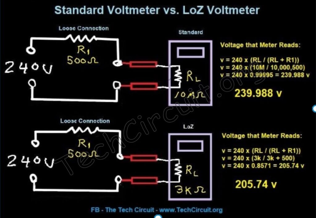
LoZ stands for “low impedance”. Using this mode puts a load on the circuit that you are testing. Normally the input impedance of the meter in the voltage testing mode is 10MΩ, which means that the circuit you are testing the voltage in will barely notice the meter. LoZ mode, however, puts a load on the circuit because it has an input impedance of 3KΩ. So when checking a voltage source such as a wall receptacle that has a loose connection upstream of it, the 3KΩ impedance is low enough to drop the voltage noticeably (because it creates a voltage divider). So this feature can help detect ghost voltages which are those that are present in a circuit when they really shouldn’t be, or high-impedance voltage sources, which read normally with a traditional voltmeter, but fail under load. Please see my full article on LoZ benefits HERE.
What Happens When you use LowZ on a Klein CL800?
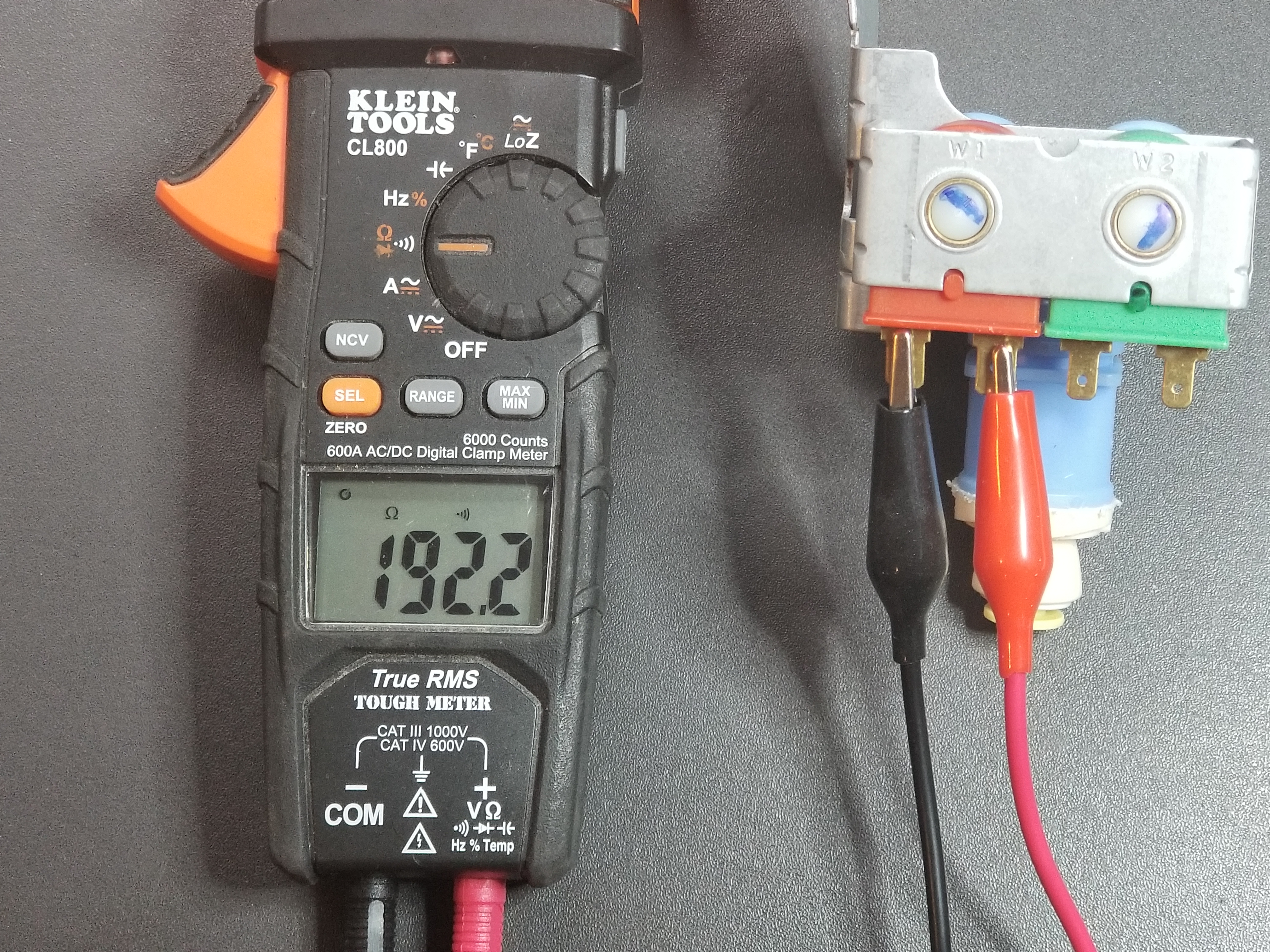
Let’s take a look below at two scenarios for an electric dryer that ran, but had no heat. The first one is using the Klein CL800 on its standard AC voltage mode to read the circuit that has an upstream loose L2 in the order of 500 Ω. The second scenario is where you used the LowZ mode to measure it.
Both methods effectively use a “voltage divider” to give you a reading. A voltage divider is when two or more resistances in a series circuit split the voltage up in a way that adds up to the total circuit voltage. For example, if you have 240v across R1 and R2 in series, the sum of the voltage across them equals 240v.
The standard formula for the voltage divider is shown in the below image. It is used for both scenarios. As you can see, using the standard voltmeter mode essentially gives you 240v – so you’d not be the wiser of what’s going on in the circuit.
However, when you use the LowZ mode, the voltage divider becomes very useful. This is depicted in the 2nd scenario in the image. The voltage you read will be 205.74v. This immediately tells you something is weak with either L1 or L2. You can then use the LowZ function to test L1 to N or L2 to N to determine which line is weak. You may already intuitively know though, that since the dryer had no heat, the problem is likely on L2, because if it was on L1, the dryer likely would not have even started (the motor typically gets its voltage from L1 to N.
Using LoZ to Determine the Upstream Loose Connection Resistance
Using your voltage reading to determine the value of the loose upstream connection may be useful information for the follow-up electrician. It may help them know what to look for based on what resistance is typical for given failures. Here’s how to do it.
With a little algebraic rearrangement of the the standard voltage divider formula, we have:
R1 = RL x ((Vs/VL)-1), where R1 is your upstream loose connection resistance, RL is your Klein 3KΩ LowZ input resistance, Vs is your source voltage of 240 volts, and VL is your measured voltage across RL with your Klein LowZ meter setting.
So for Case 2 in the image (LowZ), you have R1 = 3000 Ω x ((240v/205.74) – 1) = 499.6 Ω, which matches the example resistance we used.

AC Current
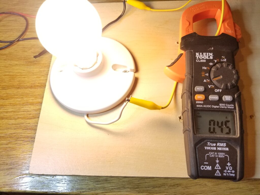
AC current is tested non-invasively using the meter’s clamp. Simply clamping around a single conductor (not both) will allow the meter to read the AC current flowing through a wire. Like most clamp-meters, the CL800 uses a “current transformer” (where the subject conductor is a one-turn primary winding), which allows the meter to provide a reading that is directly proportional to the measured current. This is because all wires with current flowing through them are surrounded by a magnetic field, the strength of which, is proportional to the current. I have measured different levels of known current with this feature and found it to be within the stated accuracy of 2%.
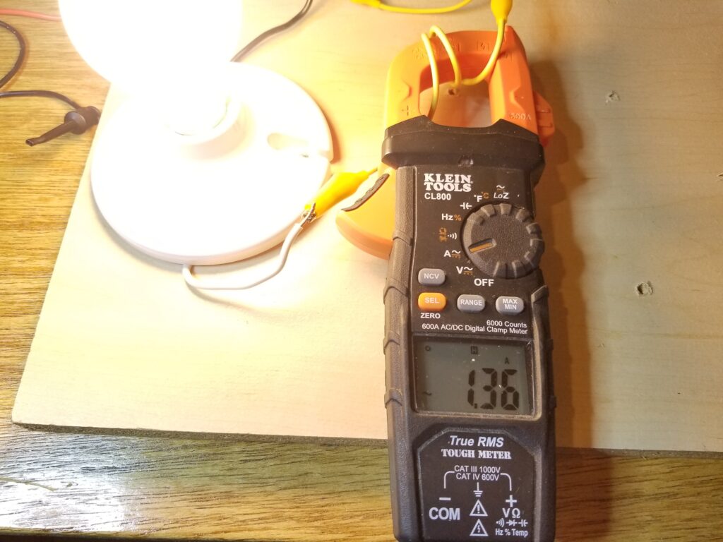
Using the clamp-meter, you can even measure low value currents at the bottom end of the meter’s range by looping the subject wire around the clamp a number of times that you want to multiply the current by. For example, if you want to read a current of 0.45 amps, you can get more accuracy by looping the wire 3 times, taking the reading (in this case 1.36 amps), and the dividing by 3. This method is illustrated in the images below:
DC Current
Traditionally, DC current would need to be tested by breaking into the circuit with your meter. The Klein CL800 has the capability to read DC current non-invasively via the clamp by using a Hall Effect sensor. Hall Effect sensors are capable of measuring static (non-changing) magnetic fields and are ideal for interpreting DC current. All wires with current flowing through them have a magnetic field surrounding them regardless of whether the current is AC or DC. The strength of this magnetic field is proportional to the current through the wire. This is a very convenient way to measure DC current. I have tested this feature with a known DC current and found this meter’s capability to measure DC current with the clamp to be very accurate (within the 2% stated accuracy).
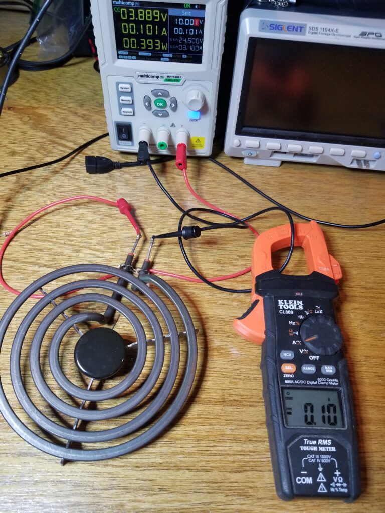
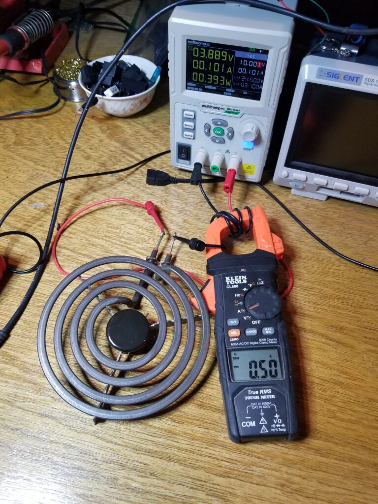
Reading small currents can be facilitated in the same way as with AC current. The example below amplifies a 0.1 amp current by a factor of 5 by wrapping the wire around the clamp 5 times. That reading is divided by 5 to give you the 0.1 amp final value.
Resistance
Measuring resistance with this meter is self explanatory. It has a good range – measuring resistances all the way down to 0.1Ω up to 60MΩ. When measuring known resistances, I found the accuracy to be within the stated 1.5% . Note however, that when using the “continuity” feature, you will need to press the “select” button to measure to get out of that mode and measure larger resistances (>50Ω). If you assume it is measuring resistance in “continuity” mode, you may erroneously deem a good resistor as being bad.
Multimeters like the Klein CL800 inject a constant current through the device under test. That current, multiplied by the resistance equals a voltage that can be directly interpreted and displayed as a resistance value.
Continuity
Continuity give you an audible “beep” of resistances less than 50Ω. Continuity is the default resistance mode of the meter. Be careful to press the select button to get out of continuity check and to measure resistances >50Ω.
Capacitance
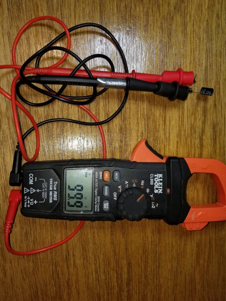
The capacitance mode is handy for measuring anything from 0.01nF (nanoFarad, or 10 billionths of a Farad) (small values found on circuit boards), up to 6000uF, which is larger than most anything you will find on appliances, HVAC systems, and most power supplies. It can measure all types of capacitors, including common electrolytics – but does not measure ESR (equivalent series resistance), which is another important metric of electrolytic capacitor health or failure.
Capacitance is measured by injecting a current source into the capacitor, and measuring the resulting voltage across it after a given amount of time. When testing a known capacitance, the meter fell within its 5% stated accuracy for the outer limits of its range and its 3% stated accuracy for he middle of its range.

CLICK HERE TO PURCHASE
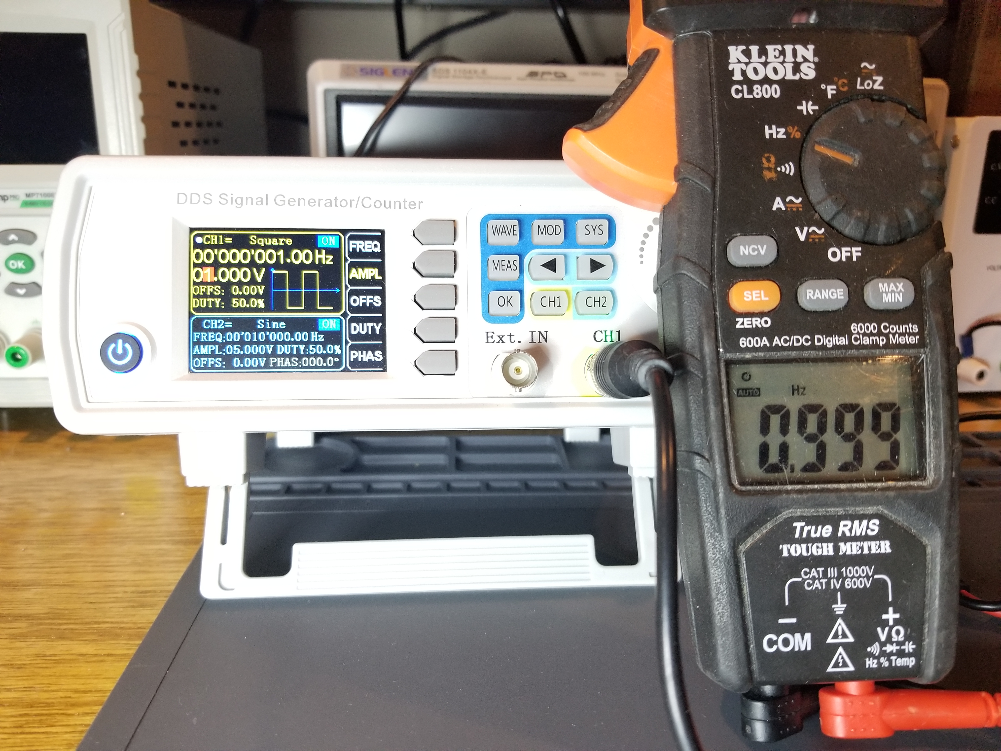
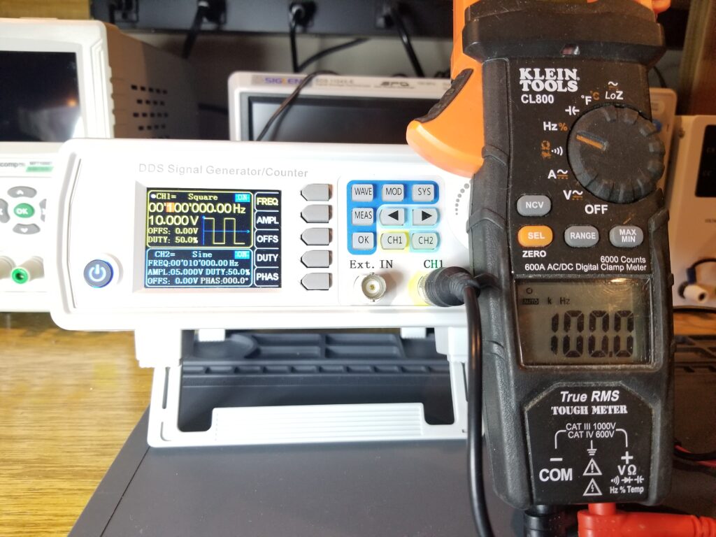
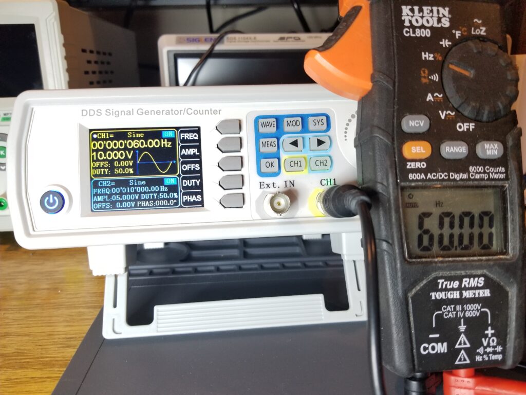
Frequency
This mode measures the cycles per second of alternating current in Hertz (Hz) from 0.001Hz (one cycle every 1000 seconds) to 500kHz (500,000 cycles per second). It can measure different waveform types such as sine, square, rectangular, and triangular. Frequency measurement is accomplished in multimeters by using an internal frequency counter, as well as a clean-up stage called a “comparator” to convert a smooth waveform (like a sine wave) into a clean rectangular wave for accurate measurement. Its frequency measurement accuracy for all of the above mentioned waveforms fell within the its stated 1% when using a digital signal generator. Below are some frequency measurements taken from a digital signal generator – a 1Hz, 1V square wave, a 100KHz square wave, and a 60Hz sine wave.
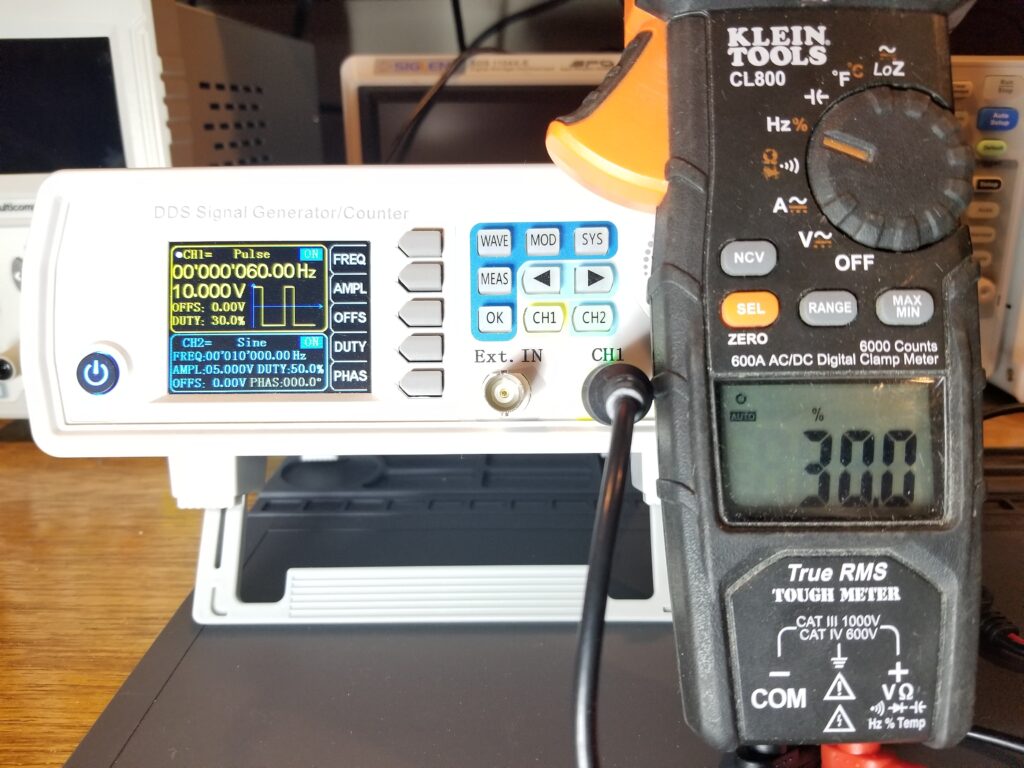
Duty Cycle
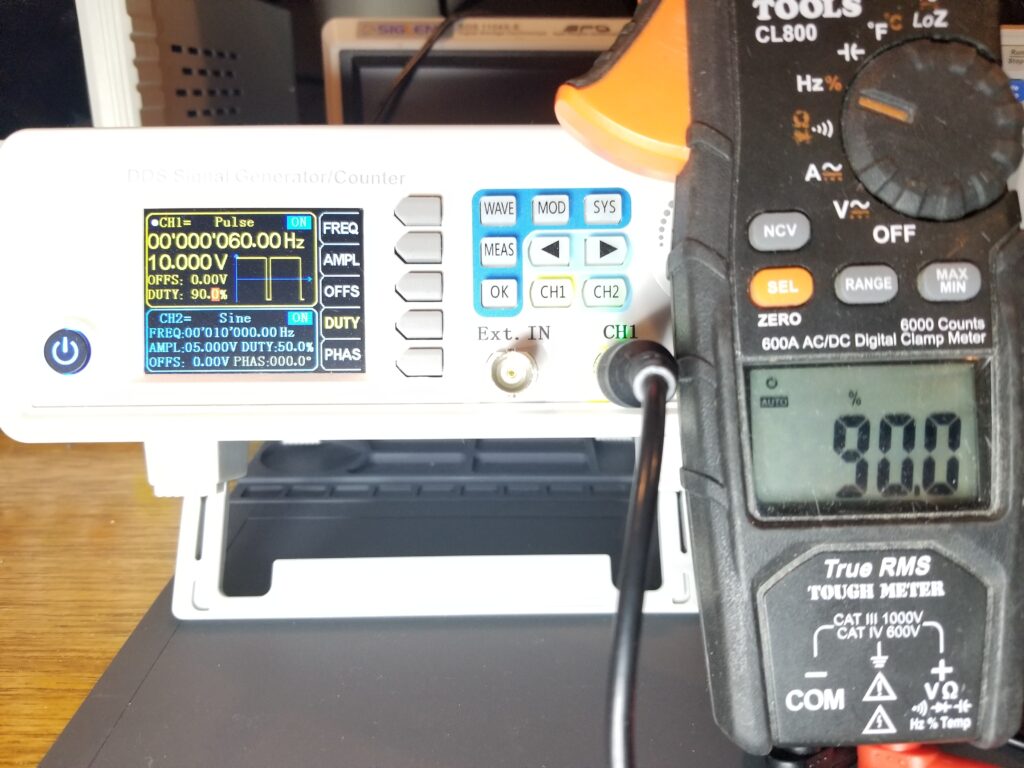
The Klein CL800 can even measure the duty cycle of rectangular waves in %. Generaly, duty cycle is the percentage a waveform’s “high-state” divided by the total period of the cycle. PWM is frequently used with DC LED lighting (especially or diming), and for signaling 3-phase motor inverters such as those in refrigerators. The CL800’s PWM % measurement accuracy fell within its stated 1.2% using a digital signal generator producing rectangular waves with a varying duty cycle. The duty cycle of other types of waves (sine, triangular) can be measured with this feature as well. Below are a few pictures of the CL800 measuring a rectangular wave of various pulse widths – a 30% duty cycle, and a 90% duty cycle rectangular wave.
Diode and Semiconductor Test
Diodes and other semiconductor junctions (like those in transistors) pass current in only one direction, once their forward voltage drop is exceeded. In order to do this, you must have a voltage that is higher than that rated forward voltage. You must then have a current limiting resistor in series with that voltage in order to protect the device under test. The DC voltage across the device under test is then measured and displayed. That is what makes up a diode and semiconductor test circuit inside of a multimeter. The Klein CL800 uses a 3V DC voltage source with current limiting resistor that limits the current to 1.5mA, which is enough to forward bias most semiconductor junctions without damaging them. Thus any semiconductor junction which includes most diodes (except microwave diodes), most bipolar transistors, and many types of LEDs that have a forward voltage drop of less than 3V DC can be tested. Zener diodes use a reverse voltage drop, and are not good candidates for the diode check unless their reverse voltage drop is less than 3V DC.
*PURCHASE THE KLEIN CL800 HERE*
A guide for testing semiconductors with the diode check mode can be found here: https://techcircuit.org/2020/05/03/semiconductor-testing-cheat-sheet/
Temperature
The Klein CL800 multimeter measures temperature in both Fahrenheit (-14°F to 1000°F) and Celsius (1°C to 548°C) using a common K-type thermocouple and an adapter. A K-type thermocouple is a junction of two dissimilar metals that when heated, generate a voltage that is proportional to temperature.
Contactless Voltage Detection
To engage non-contact voltage detection, press and hold the “NCV” button while holding the tip of the clamp near the conductor under test, and the red LED in front of the clamp will illuminate when “line” voltage is detected. I found this feature to be very sensitive, so you may not be able to easily distinguish which conductor has the live voltage on it, if there are other conductors in close proximity. The NCV feature detects the presence of an electric “field” that exists in reference to the person holding the meter. It will only detect “line” voltages, and not neutral or ground. Neutral and ground are assumed to be at approximately the same potential as the person operating the meter, and will thus not be considered “live”.
Backlight and Work Light
The backlight and work light work simultaneously by pressing the “Hold” button on the right side of the meter to the upper right of the selector knob for one second. The backlight increases the display visibility in low light conditions. The work light produces a small amount of light that comes in handy if you don’t have a flashlight within reach.
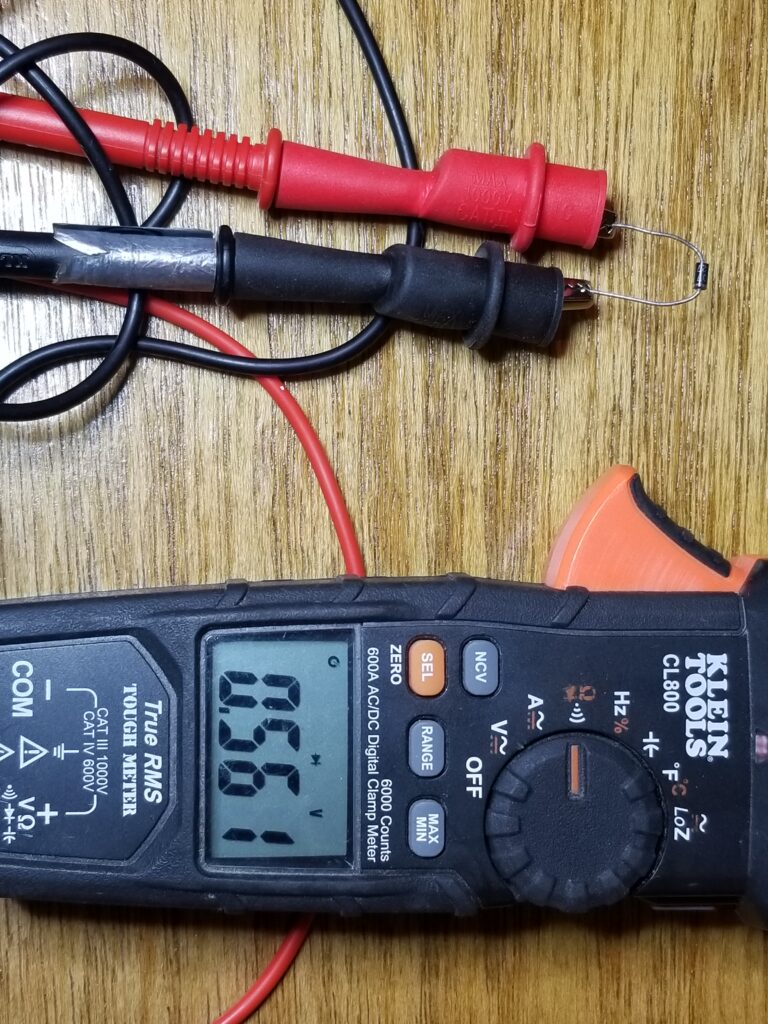
Natural Two Handed Operation
The CL800 has a test lead holder so that you can hold the multimeter in one hand (as one test lead) and the other test lead in the other hand. This ergonomic approach allows you to have the meter within visual range without having to find a place to hang it or set it down.
Pros and Cons
Pros
The CL800 is a rugged meter – built to take a beating. It has just about every function a field technician would need for appliance repair and HVAC (besides dedicated multiple temperature measurement inputs). It even has extended features like a DC clamp meter, contactless voltage detection, and duty cycle measurement. Most all of the functions fell within the stated accuracy when compared to a Fluke 110, an Amprobe 530, a digital signal generator, and a Sigilent oscilloscope.
Cons
I found few downsides to this meter. It would be nice to have in-line current measurement (it only uses a clamp for that), as in-line measurements have their place. For HVAC use, the single input K-type thermocouple is limiting when multiple temperature simultaneous measurements may be desired. The AC RMS feature is accurate for sinusoidal and square waveforms. It was way off (as much as 50%) when measuring half and full wave rectified waveforms. To the CL800’s credit, both the Fluke 115 and Amprobe 530 were equally as far off in the measured, vs. calculated value of full and half wave rectified waveforms. Only the Sigilent oscilloscope came close to those calculated values.
One annoying feature is that if you put it on the ohms setting, it defaults to “continuity”, but will measure low value resistances. For anything over 50Ω, you need to press the “select” button. I’ve been fooled by it several times when trying to measure resistances over 50Ω and got no reading when in continuity mode – which looks very much like resistance mode.
Test Your Knowledge about the Klein CL800!
What did you learn from this article? Let’s find out with this interactive quiz.
Klein CL800 Clamp Multimeter Review and Usage Quiz
Select the best answer for each question.
Summary
The CL800 has a plethora of features oriented toward the needs of field-technicians. It seems to hit all of the bases and then some. It measures AC true RMS voltage, DC voltage, AC and DC current through its clamp, resistance, diode check, continuity, temperature, frequency, capacitance, duty cycle, and more. It’s accuracy is sufficient for most applications. It is a great all-around meter for field technicians and seems to be one of the more popular ones in use.
Reviews such as this take many hours to perform. I hope this has been beneficial in not only helping you make a decision about whether to purchase the CL800, but with understanding how multimeters work in general. I do make a commission from any sales linked from this website and do appreciate your support.
CLICK HERE TO PURCHASE THE KLEIN CL800

Video Review of the Klein CL800
Below is a comprehensive video review of the Klein CL800
If this or any other article on this website has benefited you, please consider donating here:
To DONATE to the Tech Circuit – CLICK HERE
We are a participant in the Amazon Services LLC Associates Program, an affiliate advertising program designed to provide a means for us to earn fees by linking to Amazon.com and affiliated sites.