Intro
This article, for beginning to experienced appliance technicians, explains some of the more commonly found 120v and 240v Appliance circuit topologies and describes how to perform their respective point to point voltage check diagnostics for brute-force isolating of failed components. Please note that this article is not or DIY (do it yourselfers), as it describes methods that can involves voltages that can be harmful or even fatal. This is article is for qualified technicians only.
240v Appliances
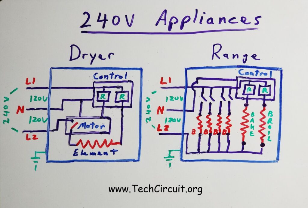
In the United States, most 240 volt appliances adhere to a common arrangement in the way they power and control loads. 240 volts is advantageous for electric heating, because elements can deliver four times the heat as with 120 volts. Below shows the typical way that both an electric dryer and a range are configured. The dryer primarily contains two 120 volt circuits and one 240 volt circuit: The main control and motor are both 120 volt circuits, the latter of which, is activated by a relay on the main control. The heating element is the 240 volt circuit that is also activated by a relay on the main control. Finally, a centrifugal switch inside the motor must be closed in order for the element to be energized.
On an electric range, the bake and broil elements are normally powered by the 240 volt circuit derived by the difference between L1 and L2. The main control is powered by the 120 volt circuit as derived from L1 to Neutral. On the main control, relays that are energized by DC voltage derived from the 120 volt circuit, are used to complete the circuit for the bake and broil elements in the 240 volt circuit. Common simple ranges like the one depicted in the image below, have infinite switches that complete the 240 volt circuit for the cooktop elements. The infinite switches use a method to “pulse” the elements with current so that the “on” vs. “off” times vary which correspondingly varies the power delivered to the cooktop elements.
120v Appliances
Most gas ranges and dryers only use 120 volts. Heat for cooking and drying is produced by gas combustion. Thus there is no need for a 240 volt supply in most cases. Below are a few (simplified) electrical configurations for gas appliances. The gas dryer consists primarily of three 120 volt circuits: The main control, the motor, and the gas ignition/valve circuit. The motor and gas circuit are each activated by relays on the main control. The gas circuit also relies on a centrifugal switch inside the motor in order to be energized. This is a safety feature that increases the chance that the blower will be pulling the flame through the funnel.
The gas range consists of four primary circuits: The main control, the bake circuit, the broil circuit, and the spark module. The spark module has four sub-circuits, which are the switches behind each knob that activates its respective cooktop burner. Note that no matter what knob is turned, all burners will “spark”.

Troubleshooting 240v Appliances
PLEASE NOTE THAT THE FOLLOWING INFORMATION INVOLVES DIAGNOSING LIVE EQUIPMENT THAT THAT MAY RESULT IN ELECTRIC SHOCK. IT IS ONLY INTENDED FOR QUALIFIED TECHNICIANS OR THOSE UNDER THE SUPERVISION OF QUALIFIED TECHNICIANS AND DONE SO AT YOUR OWN DISCRETION AND RISK.
Diagnosing 240 volt circuits is easiest when you avoid referencing ground or neutral in your measurements. This is because the circuit that involves the load (element) gets its voltage from the difference between L1 and L2, which is 240 volts. In that part of the circuit, neutral is not the return path. L1 or L2 are, depending on which side of the circuit you’re on. Also, L1 and L2 are of opposite polarity. If you lose L1 at the plug or terminal block, and you use Neutral as a test reference, L2 may travel through an element or another component. When you try to measure L1 with respect to Neutral, you may be mistakenly measuring L2.
Suppose you have a range that won’t broil. Thus the best way to troubleshoot 240 volt circuits is to measure L1 or L2 with respect to one another. Suppose you have 240 volts getting to the range terminal block, and the element “ohms out” (is good). What do you do now? There is apparently an “open circuit” in the path that contains the load. The diagram below illustrates how you can identify this open circuit by referencing L1 on the terminal block. Here are the general steps after doing the basics – checking for voltage at the range and ohming out the element – by using the “point-to point voltage difference test”:
- Identify your Subject Load (the broil element).
- Set your multimeter on AC volts.
- Connect one lead to L2 using an alligator clip.
- Turn on the broil function.
- Trace step by step through the circuit from L1 towards L2 (the return path), watching the voltage.
- Once you read 0 volts, the component just prior to your test lead is open and suspect.
- Sometimes you may read a voltage between 0 and 240 volts. This usually means a a loose connection that is allowing some voltage to still get to the Subject Load, but not enough for it to become hot.
240v Point-to-Point Voltage Difference Test Example
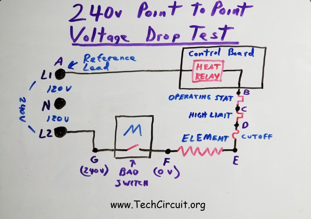
Referring to the image below – you arrive to a customer’s house with a 240v electric dryer “no heat” complaint. You do the basics. You’ve tested for 240v at the terminal block from L1 to L2 using your LowZ meter. You then open the dryer and test the element, thermal cutoff, high limit thermostat, and operating thermostat). They all test good (Element is about 10 ohms. The cutoff, high-limit thermostat, and operating thermostat are all approximately zero ohms). You now suspect either the heat relay or motor’s centrifugal switch. How can you be sure though?
You are about to find out that the motor has a bad centrifugal switch. Using the step by step point-to-point method as described above, you set your meter for AC voltage and connect your reference lead to L2 as shown in the image below. You start the dryer in heat mode. You then, (step-by-step), check the voltage at each point, starting with point B. Why? Because voltage drops favor the highest resistance. If you see 0 volts at point B, you know that the relay contacts are open (infinity resistance), but it reads 240 volts – which means the relay contacts are closed (like a switch). You go down the line to points C, D, E, and even F, but still read 240 volts. Finally, you check point G. You get 0 volts. Why? Because the centrifugal switch is open, and is the highest resistance (infinity) in the circuit.
To remedy this, you replace the motor. Now point F has 00 volts with respect to your L2 reference point. That means the motor now has 0 volts across the centrifugal switch. As it should be. The element is now the highest resistance component in the circuit because it is 10 ohms and everything else along the line has a resistance of zero ohms. So 240 volts now appears across the element.
It may be important to note that if you have a “no-bake” symptom with an electric range, you may have a bad relay. The DC voltage that energizes the relay coil is derived from a 120 volt AC circuit. However, when determining that the relay contacts weren’t making contact, you are still in the 240 volt circuit. To determine why the relay didn’t even energize or “try” to close the contacts, you are in the 120 volt circuit because the voltage that triggers the relay is derived from that circuit.
Troubleshooting 120v Appliances
Troubleshooting 120 volt appliances can be done much in the same way (above) as with 240 volt appliances. However, your return path is neutral – and it is OK to reference neutral if you want. In fact, you can use a voltage pen for quick location of open circuits. Note that 240 volt dryers normally use 120 volt motors. When troubleshooting such a circuit, you can use Neutral as your reference, even though the appliance is plugged into a 240 volt outlet.
Remember, there is rarely a reason to reference ground, unless you are looking for problems with the actual ground connection between the appliance and the breaker box , floating/loose neutral, or testing for a grounded component. There should be 0 volts voltage between ground and neutral when they are both properly connected in the breaker box. This is true of both 240 volt and 120 volt appliances. Ground is never intended to carry current on a regular basis.
Here are some specific steps that can be used to troubleshoot 120 volt appliance electrical issues:
- Check the basics – make sure you have 120v from L1 to Neutral using a LowZ meter (or with a load on the circuit)
- Based on the symptom, identify which “Load” is non-functional. This is your “Subject Load”. (Dryer won’t start: Subject Load = motor, Gas dryer no heat: Subject Load = Gas circuit, Refrigerator no defrost: Subject Load = defrost element).
- Referencing the schematic or wiring diagram, determine the circuit path for the Subject Load
- Set your meter for AC voltage and tie one lead of your meter (with an alligator clip) to Neutral where the cord comes into the unit.
- Using the other lead on your meter, trace step by step through your Subject Load circuit – checking the voltage with reference to Neutral for each point.
- If you get 120v before you reach the other (L1) side of the Subject Load, the component just prior to that point is suspect.
- If you get 120v on the other (L1) side of the Load, then your Subject Load is either energized (good) or open.
Electrical Troubleshooting Equipment
Some useful tools for electrical troubleshooting are:
A clamp-meter with LowZ, temperature, capacitance, frequency, diode check, and non-contact voltage testing (like a voltage pen).

Click Here for a suggested product that meets all of these requirements.
A voltage pen for testing the presence of AC voltage above the ground potential.

Click Here for a suggested product.
Below is a matching video on this subject:
Alphabetical Links to all Tech Circuit Articles and Blogs – CLICK HERE
Alphabetical Links to all Tech Circuit Cheat Sheets/Field References for Appliance/HVAC Techs – CLICK HERE
To DONATE to the Tech Circuit – CLICK HERE
For additional electrical and electronics learning material for field techs, visit our homepage at http://www.TechCircuit.org or our Facebook group at https://www.facebook.com/groups/746823709133603.
TC
We are a participant in the Amazon Services LLC Associates Program, an affiliate advertising program designed to provide a means for us to earn fees by linking to Amazon.com and affiliated sites.
We are a participant in the Commission Junction Affiliate Program, an affiliate advertising program designed to provide means for us to earn fees by clicking on associated links.