Why do Motors have Inrush Current?
Understanding how things work greatly impowers you when troubleshooting in the field. Let’s add a little motor theory to that knowledge.
Why is Startup Current so High?
Why is a single-phase induction motor’s starting current so high? You might just call it inrush current. It’s more complicated than that though.
To put it in simple terms, at startup or locked rotor condition, the increased current though the armature largely “nullifies” the inductance of the stator, making it look more resistive.
Here are the “hows” and “whys”:
*CLICK HERE FOR THE FREE ELECTRICITY MICRO-COURSE FOR APPLIANCE TECHNICIANS*
*CLICK HERE TO DONATE*
Locked Rotor Current
You’ve heard of “locked-rotor amps” or LRA, right? Well, when a motor is at rest, the armature isn’t moving. When you apply voltage the armature starts to move – not before a surge of current occurs though.
For fleeting moment, the circuit is experiencing LRA, and an incremental reduction of that LRA as the motor ramps up. So startup current is approximately the motor’s LRA (not withstanding the start-winding’s extra current draw). LRA is 5-6 times the run current. So for a Whirlpool dryer motor, the startup current should peak at about 20-25 amps.
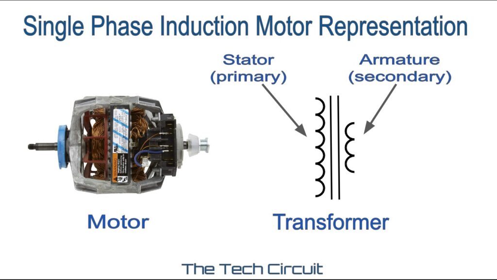
Single Phase Induction Motors are Transformers
Why though is a motor’s LRA so much higher than the run current? The answer lies in the fact that the single-phase induction motor acts just like a transformer. Referring to the images above – the stator is the primary winding, and the armature is the secondary. Given that analogy, here are some single phase induction motor facts you can add to your knowledge:
- The faster the stator’s magnetic field moves relative to the the motor’s armature, the higher the current in that armature. Thus the slower the armature, the greater the current through its windings.
- Each of a single phase induction motor’s armature windings are typically one turn, in the form of a shorted copper bar in that armature.
- Locked rotor condition in a motor, is the equivalent of shorting the secondary winding of a transformer.
- The primary winding of a transformer, as well as the stator of a motor, is an inductor.
- The more inductive the stator looks to the voltage supply, the lower the current. The less inductive, the higher the current.
- When passing AC current though an inductor, it opposes that current by inducing a voltage that is of opposite polarity from the applied voltage (or counter-EMF). This impedes the current flow, and is why AC current though an inductor is so much less than DC current, for a given voltage.
- Because of this counter-EMF, the primary winding of a transformer draws almost no current if there is no load on the secondary winding. In this case, the primary winding is acts largely as an inductor.
- However, if you put a load on the secondary (because of this thing called “mutual inductance”) the current though the secondary induces a magnetic field that starts to reduce the primary winding’s counter-EMF, making it less inductive, and increasing the current though it.
- If you short out the secondary winding, the very high secondary current induces a strong magnetic field that cancels out most of the primary winding’s counter-EMF, greatly decreasing its inductive reactance, and correspondingly increasing the current though it.
- You might think of the shorted transformer, or locked-rotor induction motor as appearing very “resistive” to the voltage supply – which greatly increases current through the transformer’s primary winding, or the motor’s stator.
Summary
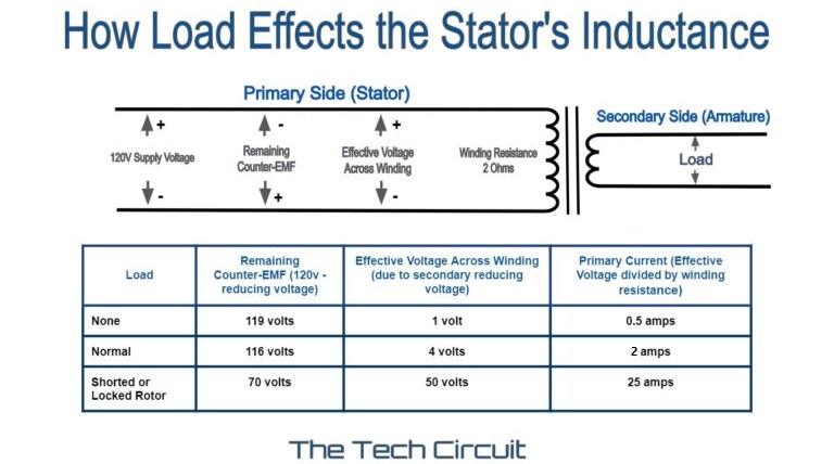
Much like a transformer, the current though a single phase induction motor’s stator (analogous to to a transformer’s primary winding) varies depending on the armature’s mechanical load (analogous to a transformer’s electrical load). The higher the load, the less inductive and more resistive the motor looks to the voltage source, and the higher stator current. At locked-rotor condition or startup, the stator looks very resistive, and a large amount of current flows through it.
Note that the stator does not look “purely resistive”. If it did, the start-up current would simply be 120v divided by the winding resistance of about 2 ohms, which would be upwards of 50 amps. This isn’t the case, though, because not all of the stator’s inductive reactance is nullified by the armature’s magnetic field.
If you found these concepts difficult to grasp, it may all “come together” by re-reading the article. I hope this helps you better understand how single-phase induction motors work.
Don’t forget:
“Diverting 10 min/day of social media time towards learning something new, is 5 hours of newfound monthly knowledge.” – SM
To DONATE to the Tech Circuit – CLICK HERE
Alphabetical Links to all Tech Circuit Articles and Blogs – CLICK HERE
Links to all Tech Circuit Cheat Sheets/Field References for Appliance/HVAC Techs – CLICK HERE
For additional electrical and electronics learning material for field techs, visit our homepage at http://www.TechCircuit.org or our Facebook group at https://www.facebook.com/groups/746823709133603.