What’s the difference between Impedance and Resistance?
We hear the term “impedance” all the time. What is it though? Why not just use the term resistance? That’s because in AC circuits, resistance, which is the opposition to current flow, is called impedance. But unlike resistance, impedance can also include the effects of capacitors and inductors.
This blog explains impedance in detail and gives you some practical examples of why it is relevant to field technicians.
Impedance relates to AC circuits
Resistance (R)
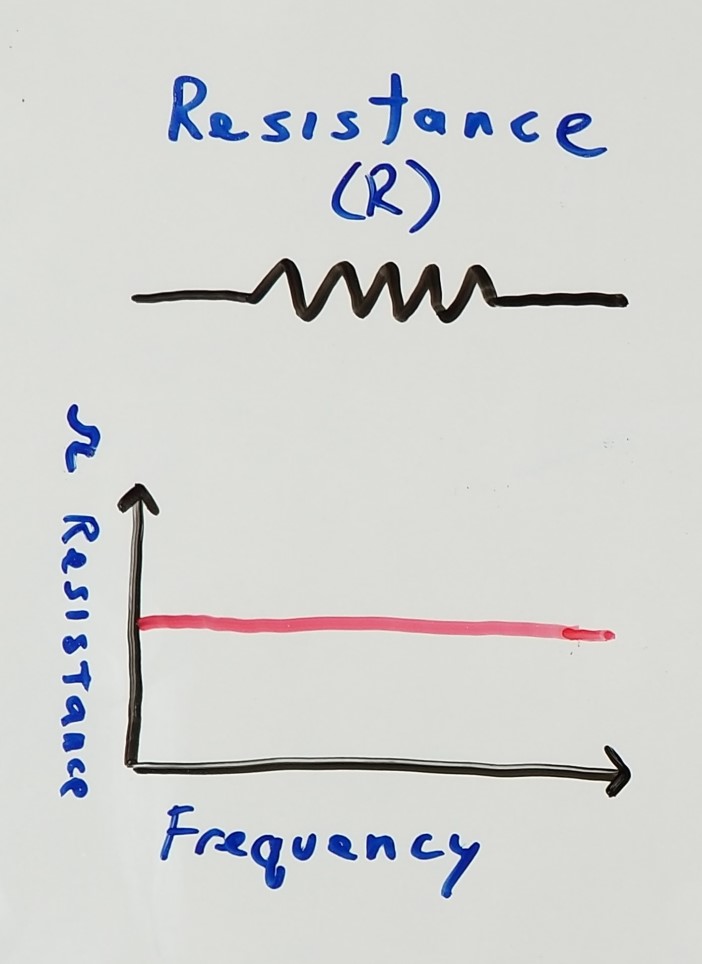
Resistance is the opposition to current flow in a DC circuit and is measure in OHMS. Resistive loads act the same in DC as they do in AC circuits. Resistance in a circuit is frequency “independent” – so no matter the frequency, the resistance is the same (ideally). In fact, a resistive load like a heating element will output the same amount of power (or heat over time) with 120v DC as it would with 120v RMS AC. That is because (RMS voltage) is the AC equivalent of DC voltage in its ability perform the above function. However, when resistance appears in an AC circuit, it’s technically referred to as impedance.
The behavior of AC circuits can drastically change however, when capacitors and/or inductors are present.
Capacitive Reactance (Xc)
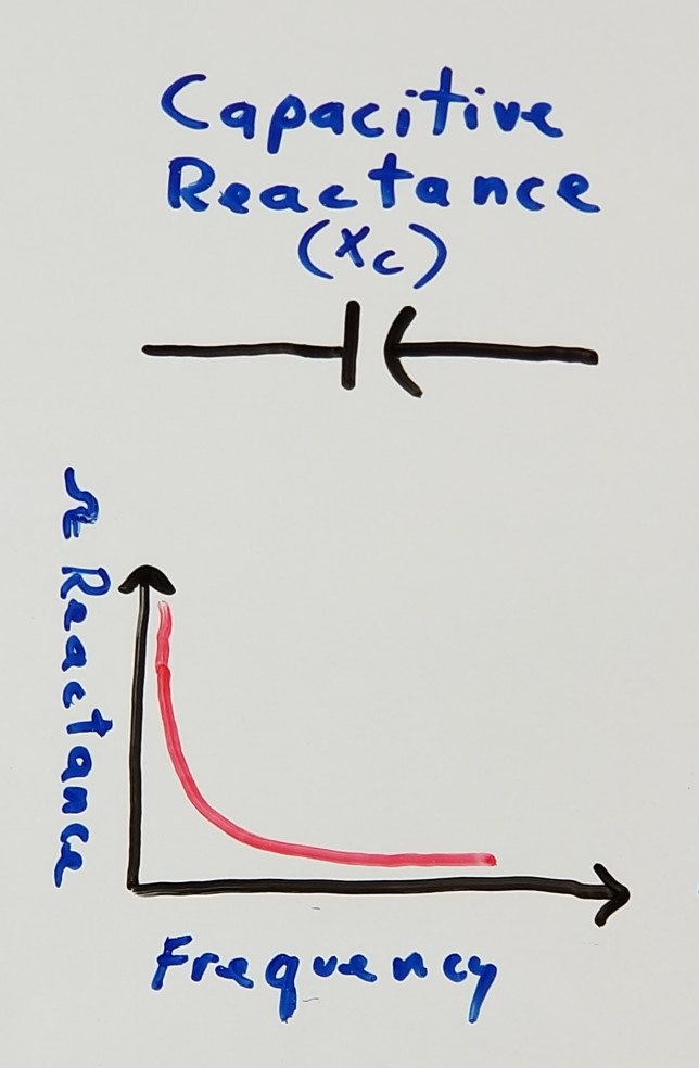
Capacitive reactance is the opposition of current flow in an AC circuit and is measured in OHMS. It is what happens when AC current is passed through a capacitor. Like resistance, capacitive reactance is a form of impedance. The relative value of this reactance in ohms is dependent on the AC current’s frequency. The higher the frequency (in hertz), the LOWER its reactance in ohms. As the frequency approaches zero hertz, the current looks more like that of a DC circuit, and the reactance becomes infinite (like an open circuit). In fact, in a DC circuit, a series capacitor would do absolutely nothing, since no current can flow through its infinite reactance. Note that capacitive reactance (Xc) in ohms and the value in F (farads) of a capacitor are not the same. The formula is simple, but will be omitted in this blog.
How Capacitors Behave in AC Circuits
Capacitors also change the way current flows though an AC circuit. They actually cause voltage to fall behind (or lag) the current. This is called a phase shift. A series capacitor in a circuit will cause the voltage across it to lag by 1/4 of a sine wave cycle (or 90 degrees) behind the current. Among countless other things, this fact is frequently exploited with induction motors because the resulting phase difference can cause stator fields to rotate.
Another important aspect of capacitors is that you can’t instantaneously change the voltage across them. Doing so (ideally) causes infinite current to flow through them – which isn’t possible. So in effect, capacitors “resist” changes in voltage across them.
Inductive Reactance (Xl)
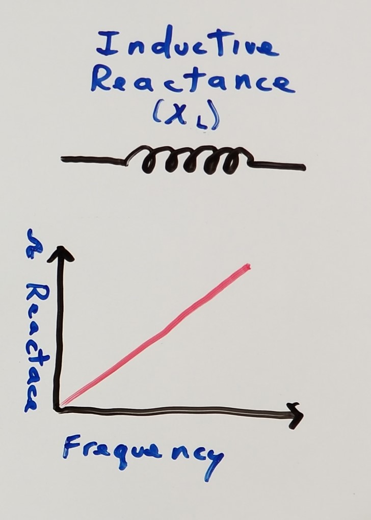
Inductors behave inversely to that of capacitors. Inductive reactance is the opposition to AC current flow and is also measured in OHMS. Also like resistance, inductive reactance is a form of impedance. The relative value of this reactance in ohms is also dependent on the AC current’s frequency. The higher the frequency (in hertz), the HIGHER its reactance in ohms (note that this is the opposite of how capacitors behave). As the frequency approaches zero hertz, the current also looks more like that of DC, and the reactance approaches zero ohms (like a closed switch). In fact, in a DC circuit, a series inductor would essentially look like a wire. It’s worth noting that inductive reactance (Xl) in ohms, and the value in H (henries) of an inductor are not the same. Albeit simple, the formula will be omitted in this blog.
How Inductors Behave in AC Circuits
Like capacitors, inductors also change the way current flows though a circuit. Unlike capacitors, inductors actually cause current to fall behind (or lag) the voltage. A series inductor in a circuit will cause the current across it to lag by 1/4 of a sine wave cycle (or 90 degrees) behind the voltage. This phase shift can be both problematic and very useful in electronics. It can cause low efficiency in motors for example, but is also beneficially exploited in many ways.
Conversely to capacitors, inductors resist a change in current. In fact, you can’t instantaneously change the current though them. Attempting to do so (ideally) causes an infinite negative voltage spike to appear across them in their effort to maintain the inertia (or status quo) of their current.
What is Impedance Though?
Impedance (Z) (also in OHMS) is the combination of all resistances and reactances in a circuit. It can contain just resistance, just capacitive reactance, just inductive reactance, or any combination of the above.
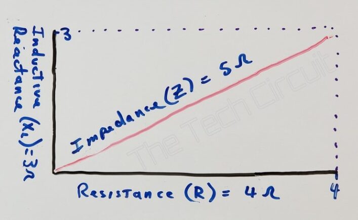
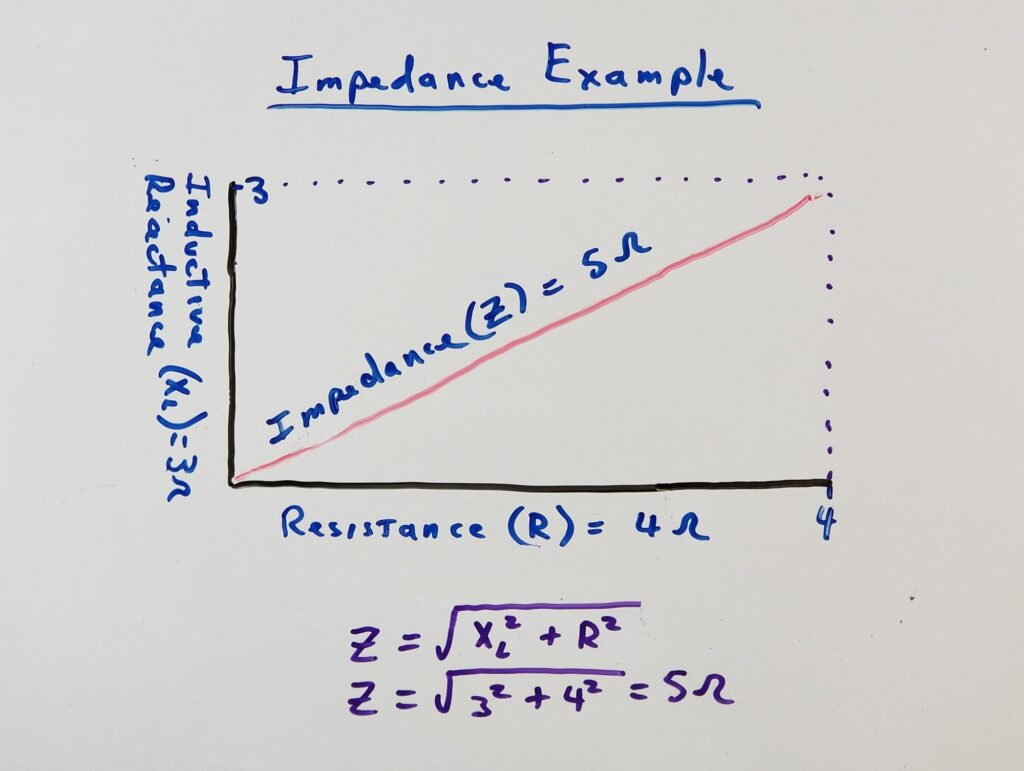
You can’t however, simply add the magnitudes of resistance, capacitive reactance, and inductive reactance to get a circuit’s total impedance. Impedance in this sense is a vector (or Pythagorean) quantity. You may find that familiar. Yes, finding the impedance of a circuit can be as simple as finding the hypotenuse of a triangle. In the example below, the impedance in a circuit with a 4Ω resistance in series with a 3Ω inductive reactance is 5Ω, not 7Ω. The example also illustrates that in a series AC circuit with inductors or capacitors, the impedance is always greater than any resistance in that circuit – which is not only important for field Technicians to understand, but should ideally become intuitive – because that reduces the current relative to a purely resistive circuit.
Those constituent parts of impedance not only determine its final opposition to current flow, but also how it affects the phase (delays or advances) of current vs voltage in that circuit.
When you use your LowZ meter, you are introducing a low impedance to the circuit. The input of that meter may just be a simple resistance (such as in the Klein CL800’s 3kΩ input resistance) or a more complex impedance that might include capacitance for different brands/models. The final outcome is that you are putting a load on the circuit based on the value (in ohms) of that impedance.
Test your Practical Knowledge of Impedance!
Understanding Impedance
Select the best answer for each question.
Summary
Like resistance, impedance is measured in OHMs and is a measure of current flow opposition – but in AC circuits. Unlike in DC circuits, impedance can include the effects of resistance, capacitors, and inductors in AC circuits. The opposition to current flow through resistance is not frequency dependent. That opposition however with capacitors and inductors is very much frequency dependent. Capacitors resist changes in voltage whereas inductors resist changes in current. The higher the frequency, the lower the capacitive reactance in ohms. The higher the frequency, the higher the inductive reactance in ohms. At DC, a capacitor looks like an open circuit, and an inductor looks like a closed circuit.
Total impedance in a series circuit can be found in the same way a finding the hypotenuse of a triangle. Although in your field, you may never want to break out a calculator – it is important to realize that capacitors and/or coils (inductors) in a series circuit will increase the impedance of that circuit, and thus reduce the current through that circuit.
One example would be the inlet valve solenoid of a refrigerator. If you statically measure its resistance with an ohmmeter (which uses DC), you may get 200 ohms for example. However, when energized with AC current, the solenoid may look like 400 ohms because of the coil’s inductance. That 400 ohms is a combination of the solenoids internal resistance and its inductive reactance. Thus, the current though the valve would be 120v/400Ω or 0.3A in an AC circuit, as opposed to 120v/200Ω or 0.6A if the solenoid was in a DC circuit – which is 1/2 of the current that you may have expected from your static resistance measurement.
Another practical example of how impedance matters is with HVAC contactors. The inductance of the coil greatly increases when the contactor closes. Why? Because as the contactor closes, the iron core is inserted in the middle of the coil – greatly increasing its inductive reactance. Without the core, the coils impedance is much less – causing a significant increase in current through it. This in turn can (and often does) burn up the contactor. You will also see this phenomenon occur with inlet valves, and solenoids that perform mechanical functions like with refrigerator dispensers, and in dishwasher drain systems. TC
“Diverting 10 min/day of social media time towards learning something new, is 5 hours of newfound monthly knowledge.” – SM
To DONATE to the Tech Circuit – CLICK HERE
Alphabetical Links to all Tech Circuit Articles and Blogs – CLICK HERE
Links to all Tech Circuit Cheat Sheets/Field References for Appliance/HVAC Techs – CLICK HERE
For additional electrical and electronics learning material for field techs, visit our homepage at http://www.TechCircuit.org or our Facebook group at https://www.facebook.com/groups/746823709133603, or our YouTube Channel
at https://www.youtube.com/c/TheTechCircuit
We are a participant in the Amazon Services LLC Associates Program, an affiliate advertising program designed to provide a means for us to earn fees by linking to Amazon.com