Understanding Ohm’s Law is not only essential for building a strong foundation in electrical theory but also serves as a valuable tool for diagnosing electrical problems. Although many technicians know about Ohm’s Law, some may not use it because they don’t see its relevance or don’t realize when it can be helpful. Ohm’s Law allows you to calculate current, voltage, or resistance, helping you identify unknowns and speed up the diagnostic process. This article will provide practical examples of how Ohm’s Law can be a powerful tool for diagnostics by expounding on the following case studies.
- Electric dryer takes too long to dry due to an unintended series load.
- Determining which coil in a dual element is the high heat coil.
- Electric dryer takes too ling to dry because one of the coils in a dual element is open and – how to determine this without disassemblIng.
- If an electric range is overheating – how to find out from the terminal block if there’s a stuck relay on the board.
- Find the expected resistance of a bake element if you only know the wattage.
Also, take the quiz at the end of this article to test your knowledge! Let’s now look at the above examples in more detail.
Disclaimer:
THIS BLOG IS INTENDED FOR APPLIANCE TECHNICIANS AND IS FOR INFORMATIONAL PURPOSES ONLY. ALWAYS FOLLOW PROPER SAFETY PRECAUTIONS WHEN WORKING WITH ELECTRICITY. USE THE CONCEPTS DISCUSSED AT YOUR OWN RISK. THE AUTHOR ASSUMES NO RESPONSIBILITY FOR ANY OUTCOMES, ERRORS, OR OMISSIONS.
Case #1: Electric Dryer Taking too Long to Dry
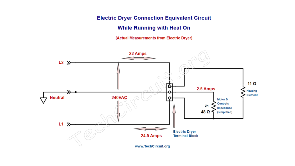
In this example case, the dryer was intermittently taking too long to dry. The customer also noted that that it wasn’t getting very hot. A dryer needs to get clothes to a designed temperature in order to promote evaporation, and ultimately exhaust the moisture outside. If the drum only gets “warm”, that process is severely compromised and delayed. The heating circuit for this particular dryer consists of an 11 Ω heating element (Whirlpool 279838, for example), and is the only circuit in the dryer that uses the L2 electrical line (connected at the terminal block). This provides us an opportunity to determine the health of that circuit by just checking the current draw on L2 with a clampmeter.
The typical 11 Ω (runtime – when hot) resistance of the element should cause an (Ohm’s law (I = V/R) amount of current to flow through the heat circuit (through L2), which is 240 V / 11 Ω = 22 A. This is how much current draw we would expect to find on L2 when the heat is cycled on. The schematic diagram below depicts the primary loads of a of a properly functioning electric dryer. Note that the motor circuit is shown to illustrate that the only the heating circuit utilizes the L2 supply line.
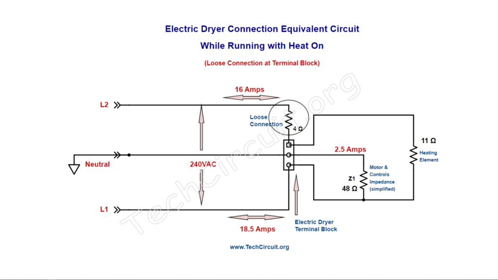
In our case, though, when we measured the current draw, we found 16 A at L2. How could that be though if our element is 11 Ω? We can determine the total resistance (or impedance, if you will) of the heat circuit by using Ohm’s Law again. That would be R=V/I = 240 V/16 A = 15 Ω. So where did the other 4 Ω come from? We inspected the terminal block and noticed that the L2 connection was burned up, which was causing intermittent heat. That connection had a high resistance (4 Ω high compared to the 0 Ω it should be), which was robbing the element of some of its voltage and thus needed power. So using Ohm’s Law, we were able to know there was extra resistance in the circuit, which prompted the terminal block inspection. Below depicts the same dryer circuit with the loose terminal block connection (circled).
Case #2: Electric Dryer Ohming out Dual Element
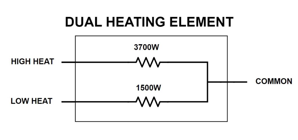
In this case study, you’re in the field and replace the element assembly in a dual-element dryer but forget which wire goes to what terminal. You know which one is common, since that comes from the motor’s centrifugal switch and is the heat circuit’s L2 return path. However, you don’t remember which wire goes to the main or low heat element terminals. The schematic calls out the wattage of each coil and the color wire that should go to each. That is 3700 W (blue wire) and 1500 W (white wire). To solve this problem, you can determine the expected resistance of each coil by using Watts law directly, or both Watts law and Ohm’s law. Let’s use both Watt’s law and Ohm’s law in this case, to find the expected current through each coil. This would be I = P/E = 3700 W / 240 V = 15 A (approx). For the other coil, it would be 1500 W / 240 V = 6 A, approx. From these amperages, we can use Ohm’s law to find the expected resistance which would be R=V / I = 240 V / 15 A = 16 Ω, and 240 V / 6 A = 40 Ω. Since resistance increases 10-15% when hot vs. cold, these values are approximate. However, they are so greatly different from each other, it will be no problem determining which coil is the 3700 W one and the 1500 W one.
We then measure the resistances, and are easily able to determine which coil is which. Referring to the schematic, we connect the blue wire to the 16 ohm (3700 W) coil and the white wire to the 40 ohm (1500W) coil.
Note that alternatively you could have used only Watt’s law with the V² / W formula to find the resistance. So for example, using this formula, the resistance of the 3700 W coil would be (240 V x 240V) / 3700 W = 57600 / 3700= 16 Ω (approx).
Case #3: Another Electric Dryer Taking too Long to Dry
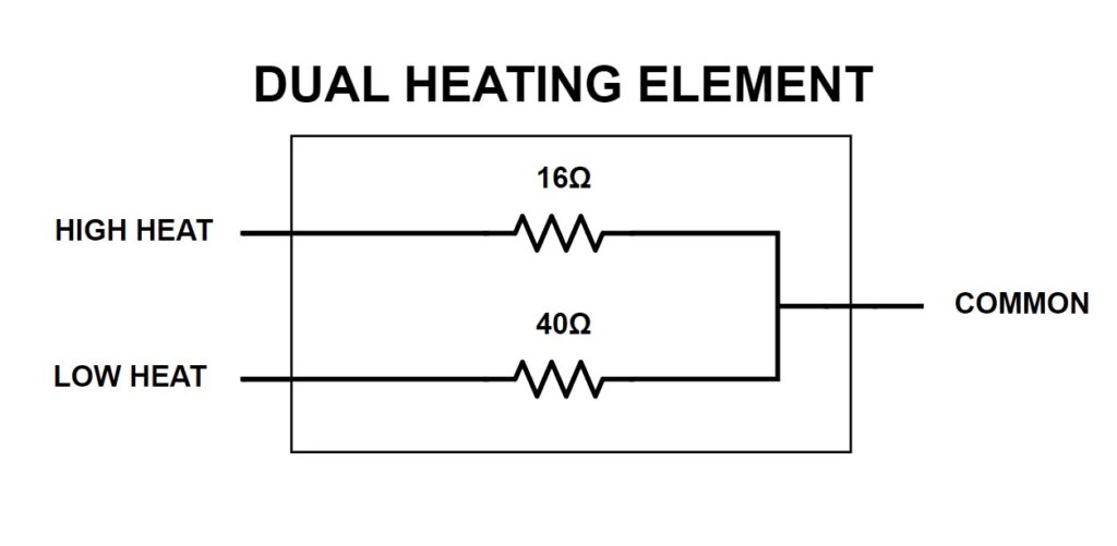
In this case, the electric dryer had a dual element (like the one in the previous case, but used to illustrate a different concept) in which both coils were used during high heat, and only one coil for low heat. The main coil was rated at 16 Ω and the low heat coil at 40 Ω. The customer complaint was that was taking too long to dry during high heat and worked as expected during low heat.
You suspect that one of the coils is burned out, but would have to fully disassemble the dryer to find out. Alternately, you could monitor the current on L2 and ascertain which coil in the element, if any was open when it should be energized. To find out the expected current draw of each coil based you can use Ohm’s Law with your known values of voltage and resistance. If the main coil was rated at 16 Ω , as mentioned above, then using I = V / R, you can determine that the current draw of the main coil should be 240 V / 16 Ω = 15 A. Likewise, you can do the same for the other coil knowing the its resistance, which would come out to 240 V / 40 Ω = 6 A.
Note that resistance slightly increases when the coils heat up, so the current will be about 10% less than your calculation.
You set the cycle on high heat where both coils should be energized, and measure the current at L2 and are getting 5.5 A. This matches our calculation for the low heat coil. If both coils were intact, the current from both coils would be additive and you would read close to 20 amps. Thus you can infer from this measurement that the main coil is open, and that the low heat coil is ok.
Since both coils are on the same assembly, the entire assembly would need replacing. However, you were able to determine this without disassembling the dryer and could give your customer an estimate based simply on your L2 readings.
Note that in some cases, yes, a burned/open wire could be the cause, but at least you an get your customer’s pledge to pay for the worst case scenario before disassembling.
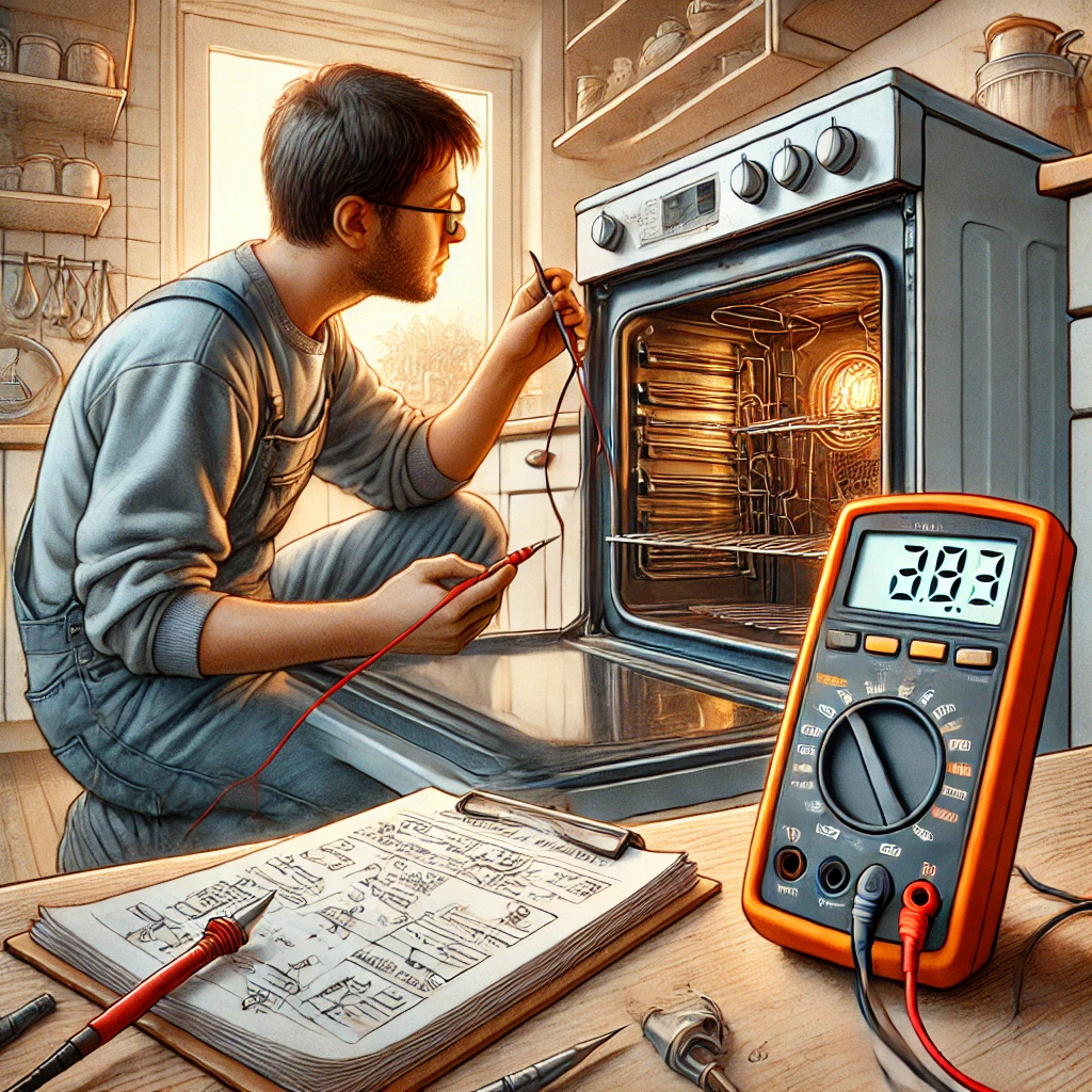
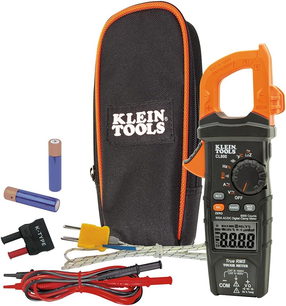
Recommended Multimeter for Field Service
Below is the multimeter I recommend for field service as it encompasses all features imaginable for appliance and HVAC repair. Please note that these articles take time and effort to write, and I do receive commissions from every sale. You can help us offset our time by clicking the link or picture below to purchase this meter or any other test equipment. CLICK HERE TO PURCHASE
Case #4: Electric Range Overheating
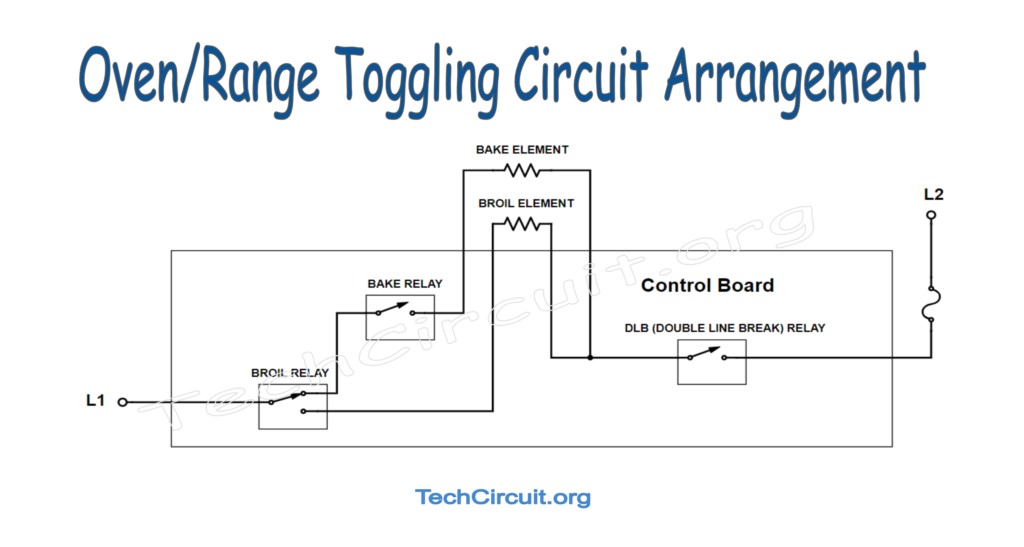
In this case, the customer complaint was that the range was overheating, throwing a code, and burning the food on top. Knowing that in most electric ranges, the bake and broil elements work together to help accelerate preheat, and more evenly cook the food. But instead of coming on at the same time, they are designed to “toggle”. This saves energy and utilizes their respective stored heat to accomplish the above goal.
Because the broil element tends to draw more current, the broil relay often fails. One of its common failure modes is fused contacts. This causes the broil element to stay on for the entire cook cycle, rather than to toggle back and forth w/r to the bake element.
Knowing that (per the tech sheet), the bake element resistance is about 25 Ω, and the broil element about 17Ω, we can ascertain how much current should be flowing through L2 at the terminal block during the bake cycle. Since both elements should toggle, for the bake element we should get I = V / R = 240 V / 25 Ω = 9 A, and for the broil element 240 V / 17 Ω = 14 A. We should see these readings toggle back and forth on our clampmeter. However, if the broil relay was fused, because of the logical arrangement of the relays, we would see the current only from the broil element with our clampmeter, or a continuous 14A. In the less common ovens where a different relay arrangement allows both elements to be energized simultaneously, a fused broil relay would result in the sum of both elements’ currents, or around 24 A.. In either case, we would suspect a bad control board due to a fused broil relay.
Case #5: Ohming out Bake Element
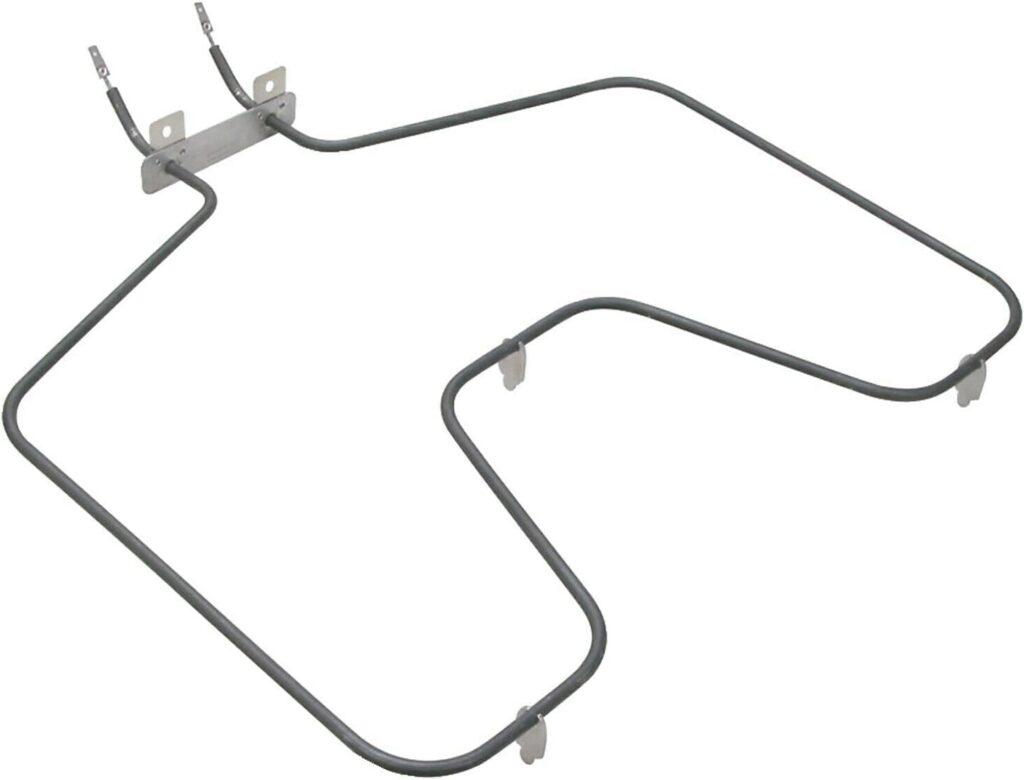
You go on a call where the complaint is that the electric range is taking a long time to preheat. You want to “ohm out” the bake element but don’t know the expected resistance. I have seen this question posed mutiple times in the Appliance Technician groups. The tech sheet calls out the element’s wattage at 2585 W. From here, you can use Watt’s law directly to determine the resistance, or to determine the expected current, and then use Ohm’s law to find the resistance. Since this blog is about Ohm’s law, let’s do the latter first. Watt’s law states that P = V x I. So I = P / V = 2585 W / 240 V = 10.8 A. Ohm’s law states that V = I x R or R = V / I. So R = 240 V / 10.8 A = 22.2 Ω. Note that as the element heats up, its resistance increases slightly due to its temperature coefficient. So the 22.2 Ω at the rated wattage is after the resistance change. So a more accurate expectation of expected resistance will be that value minus 15%. So the measured resistance when cold may be as low as 22.2 Ω – (22.2 x .15) = 18.8 Ω, or thereabouts. To simplify things, for heating elements, if your measured resistance is within 2 to 5 Ω less than your resistance based on rated wattage, you’re fine. Any measurement between 17 Ω to 20 Ω should be fine.
Using Watt’s law directly, you could apply the P = V² / R o R = V² / P formula to find the run-time resistance. That would be (240 V x 240 V) / 2585 W = 22.2 Ω. As with the previous method, you would then subtract your 2 to 5 Ω to compensate for the element’s temperature coefficient and should again measure between 17 Ω to 20 Ω.
Test Your Knowledge!
Test your comprehension of this material, and see how high you can score. The quiz answers are at the end:
Quiz: Ohm’s Law in Appliance Repair
- What is the primary purpose of using Ohm’s Law in appliance repair?
- A) To calculate the age of an appliance
- B) To determine the color of appliance wires
- C) To calculate current, voltage, or resistance
- D) To estimate repair costs
- In Case #1, what was the measured current draw on L2 that indicated an issue?
- A) 22 A
- B) 16 A
- C) 11 A
- D) 24 A
- What was the expected current draw on L2 for a properly functioning dryer in Case #1?
- A) 16 A
- B) 11 A
- C) 22 A
- D) 24 A
- What additional resistance was found in the heating circuit due to a burned L2 connection in Case #1?
- A) 2 Ω
- B) 4 Ω
- C) 6 Ω
- D) 8 Ω
- In Case #2, what is the expected resistance of the 3700 W coil?
- A) 16 Ω
- B) 24 Ω
- C) 32 Ω
- D) 40 Ω
- What is the expected resistance of the 1500 W coil in Case #2?
- A) 16 Ω
- B) 24 Ω
- C) 32 Ω
- D) 40 Ω
- How can you determine which coil is the high heat coil in a dual-element dryer?
- A) By measuring the voltage
- B) By measuring the resistance
- C) By measuring the current
- D) By measuring the power
- In Case #3, what was the customer’s complaint about the electric dryer?
- A) The dryer was overheating
- B) The dryer was taking too long to dry
- C) The dryer was making noise
- D) The dryer was not starting
- What is the expected current draw of the main coil (16 Ω) in Case #3?
- A) 6 A
- B) 10 A
- C) 15 A
- D) 20 A
- What is the expected current draw of the low heat coil (40 Ω) in Case #3?
- A) 6 A
- B) 10 A
- C) 15 A
- D) 20 A
- How can you determine if a coil in a dual-element dryer is open without disassembling?
- A) By measuring the voltage
- B) By measuring the current on L2
- C) By measuring the resistance
- D) By measuring the temperature
- In Case #4, what issue can cause an electric range to overheat?
- A) A faulty thermostat
- B) A stuck relay on the control board
- C) A broken heating element
- D) A loose power cord
- How can you check for a stuck relay on the control board from the terminal block?
- A) By measuring the voltage
- B) By measuring the current
- C) By measuring the resistance
- D) By measuring the temperature
- How can you find the expected resistance of a bake element if you only know the wattage?
- A) By using Ohm’s Law
- B) By using Watt’s Law
- C) By using both Ohm’s Law and Watt’s Law
- D) By measuring the resistance directly
- Which of the following is an example of how Ohm’s Law can save time during appliance repair?
- A) Testing heating elements for the correct resistance
- B) Diagnosing faulty motors based on current draw
- C) Identifying bad connections causing voltage drops
- D) All of the above
Answers:
- C) To calculate current, voltage, or resistance
- B) 16 A
- C) 22 A
- B) 4 Ω
- A) 16 Ω
- D) 40 Ω
- B) By measuring the resistance
- B) The dryer was taking too long to dry
- C) 15 A
- A) 6 A
- B) By measuring the current on L2
- B) A stuck relay on the control board
- A) By measuring the voltage
- C) By using both Ohm’s Law and Watt’s Law
- D) All of the above
Conclusion
This blog explained examples of how Ohm’s law can be used in appliance repair and other field-technician disciplines to help diagnose and solve various electrical problems. The example cases were used by the author at some point in the field, and can easily apply to other field technicians In fact, the reader, having fully understood the approaches and advantages of the blogs example cases, will be able to not only apply Ohm’s (or Watt’s) law to such cases, but will be able to formulate their own approaches and uses of Ohm’s law to the extent that it may improve or expedite their on-site diagnosis.
Don’t forget:
“Diverting 10 min/day of social media time towards learning something new, is 5 hours of newfound monthly knowledge.” – SM
To DONATE to the Tech Circuit – CLICK HERE
Alphabetical Links to all Tech Circuit Articles and Blogs – CLICK HERE
Links to all Tech Circuit Cheat Sheets/Field References for Appliance/HVAC Techs – CLICK HERE
For additional electrical and electronics learning material for field techs, visit the following links:
Homepage at http://www.TechCircuit.org
Facebook group at: https://www.facebook.com/groups/746823709133603
Youtube Channel: https://www.youtube.com/@TheTechCircuit
We are a participant in the Amazon Services LLC Associates Program, an affiliate advertising program designed to provide a means for us to earn fees by linking to Amazon.com and affiliated sites.