What is a Voltage Source?
Not all voltage sources are created equal. For example, a 12V car battery doesn’t provide enough voltage to electrocute, but sufficient current to crank a 400A car starter. This would be called a relatively strong voltage source. On the other side of the spectrum, a taser, for example outputs 50,000 volts, but can only supply 2.1 mA of current. Despite its high voltage, the TASER’s substantial internal impedance limits its current delivery, classifying it as a weak voltage source. On a side note that will be explained later, there are plenty of voltage sources that could cause electrocution. Neither of the above examples qualify though.
So what determines how strong or weak a voltage source is? It’s not only about the magnitude of the voltage, but about internal series resistance, or (impedance in the case of AC sources). Let’s explain.
Ideal Voltage Source
The ideal voltage source doesn’t exist, but represents the theoretical baseline on which the practical voltage source is described. The ideal voltage source has no internal series resistance. Regardless of the current demanded by the load, the ideal source experiences no internal voltage drop. This means that the ideal voltage source can supply infinite current to a load as depicted in the below image.

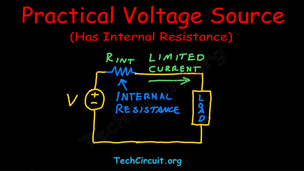
Practical Voltage Source
All voltage sources have some internal series resistance or impedance. For DC voltage sources, internal resistance comes into play, and for AC sources, internal impedance is the determining factor.
In the case of batteries, such internal series resistance can primarily be due to:
- Effective resistance of the battery’s chemistry
- Resistance of internal connecting wiring
For AC voltage sources, like a 120v residential outlet, the internal series impedance can be due to:
- Wiring resistance – wires with lower gauge numbers (thicker wires) have less resistance, while higher gauge numbers (thinner wires) have more resistance.
- Connection points from the breaker box, junction boxes, and at the outlet.
- Breaker panel resistance, such as the circuit breaker’s connection to the bus-bar.
- The utility transformers output impedance.
The image below depicts the practical voltage source.
The Voltage Divider
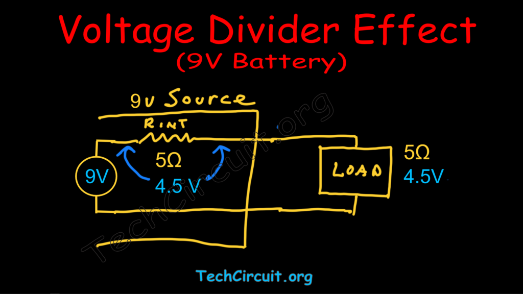
An interesting, but fundamental phenomenon occurs when a practical voltage source forms a circuit with a load. This is a voltage divider. According to Kirchhoff’s Voltage Law (KVL), the sum of voltage drops across components in a series circuit equals the total source voltage. Thus, when you connect a practical voltage source to a load, some of that source’s voltage appears across the load, and the rest appears across its internal resistance. Let’s look at an example. A 9V alkaline battery has an internal resistance of about 5 ohms. This means that when you connect it to a 5 ohm light bulb, only 4.5 volts will appear across the light bulb and the other 4.5 volts is lost across the battery’s effective internal resistance. The image below depicts this.
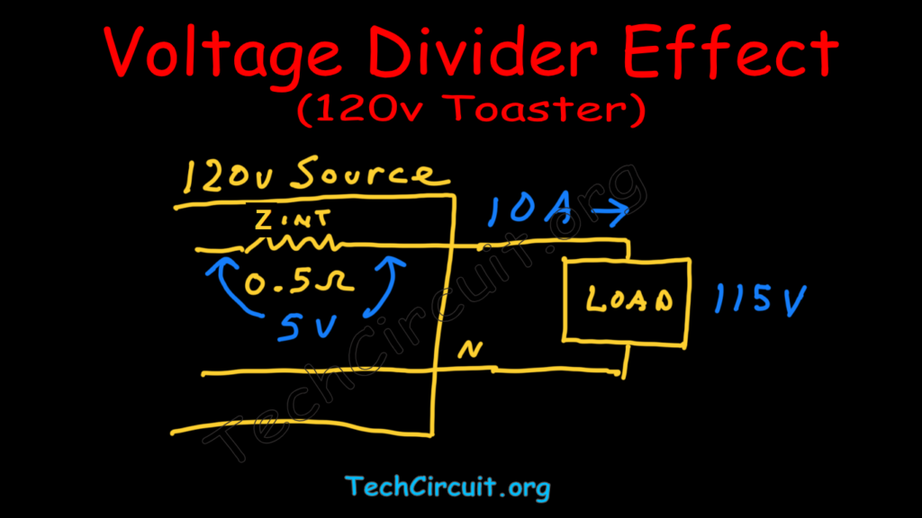
Here’s another example – except with an AC voltage source, so we’ll use the term “impedance” and use the designator “Z”, instead of “R”. A 120v residential outlet has an upstream internal impedance of about 0.5 ohms. This means that when you plug in a 10 ohm toaster, the circuit current is I = V/Z = 120 V/(10 + 0.5) ohms = 11.4 amps. This means that the voltage the toaster actually gets is V = I x Z = 11.4A x 10 ohms approximately 114v (let’s round to 115v for simplicity). The voltage lost in the residential voltage source’s wiring is the remainder of the source voltage or 5v. The image below depicts this.
How to Determine a Voltage Source’s Internal Series Resistance or Impedance
Knowing that a voltage divider is formed between a practical voltage source and its load, we can easily determine the internal resistance or impedance of said source. Let’s take the 9v battery example for instance. Knowing that the output should be 9v, and you connect it to the 5 ohm light bulb, all you need to do is measure the voltage across the load. If you measure 4.5v across that load, you know your current is I = V/R = 4.5/5 = 0.9A (until that battery quickly dies!). Now to find the effective internal series resistance of the battery, simply use Ohm’s Law again (R = V/I). In this case “V” will be the voltage across the internal resistance of the battery. Per KVL, this would be 9v minus the 4.5v across the load. This leave 4.5v across that resistance. Thus, you have R(internal) = 4.5v / 0.9A = 5 ohms.
This can be simplified using the equation:
R(internal) = ( V(source) – V(load) ) / I(load)
Where:
- I(load) is the current through the load
- R(internal) is the internal resistance
- V(source) is the source voltage
- V(load) is the voltage across the load
Electrocution Revisited
Why can a 120V outlet cause electrocution, while a 50,000V taser typically cannot? It’s all about the voltage source’s ability to source continuous current. As little as 50V can cause electrocution (because of the human body’s internal resistance is as low as 1000 ohms), but only if that 50V can supply 50mA or greater. Sparing you of the math, a taser’s effective internal resistance is very high – about 14 million ohms. The 120v outlet’s impedance, as you may remember, is about 1/2 of an ohm. Thus, most of the taser’s 50,000 volts is lost across its internal resistance, whereas most of the 120v source’s voltage appears across the human body. In fact, the average voltage supplied by the taser is actually quite low. When under load, it is around 1500 volts, but is pulsed. The average voltage is actually much lower. So the fun fact here is that the 120v outlet supplies much more average voltage to the load (the human), than the taser does.
Test Your Knowledge!
Anatomy of a Voltage Source Quiz
Please select the most appropriate answer for each question. Some questions may include options like "All of the above" or "None of the above." Good luck!
Conclusion
The voltage source is a fundamental component of an electrical circuit. Other than the magnitude of that voltage, the source’s ability to energize the intended circuit, however, critically depends on a key factor that all practical voltage sources have in common – internal series impedance. This limiting factor is what separates the ideal voltage source from the practical one. Ideal voltage sources have no such impedance, and can source unlimited current. Practical voltage sources, however, live in the real world, and are limited in their ability to do so. From button-cell batteries and 240V residential outlets to car batteries, a wide spectrum of practical voltage sources exists, differentiated not only by their voltage level but also by the vast range of internal impedances that help define these sources and their ability to perform specific tasks.
Don’t forget:
“Diverting 10 min/day of social media time towards learning something new, is 5 hours of newfound monthly knowledge.” – SM
To DONATE to the Tech Circuit – CLICK HERE
Alphabetical Links to all Tech Circuit Articles and Blogs – CLICK HERE
Links to all Tech Circuit Cheat Sheets/Field References for Appliance/HVAC Techs – CLICK HERE
For additional electrical and electronics learning material for field techs, visit the following links:
Homepage at http://www.TechCircuit.org
Facebook group at:
https://www.facebook.com/groups/746823709133603
Youtube Channel: https://www.youtube.com/@TheTechCircuit
We are a participant in the Amazon Services LLC Associates Program, an affiliate advertising program designed to provide a means for us to earn fees by linking to Amazon.com and affiliated sites.