This blog will describe step by step, how the standard Whirlpool gas dryer ignition circuit works, along with its common failures and associated diagnostic approaches.
Disclaimer:
THIS BLOG IS INTENDED FOR APPLIANCE TECHNICIANS AND IS FOR INFORMATIONAL PURPOSES ONLY. ALWAYS FOLLOW PROPER SAFETY PRECAUTIONS WHEN WORKING WITH GAS AND ELECTRICITY. USE THE CONCEPTS DISCUSSED AT YOUR OWN RISK. THE AUTHOR ASSUMES NO RESPONSIBILITY FOR ANY OUTCOMES, ERRORS, OR OMISSIONS.
Valve and Ignition Circuit Overview
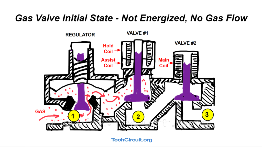
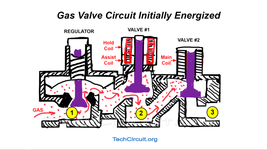
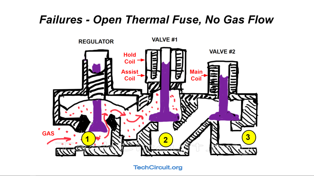
The gas valve assembly consists of a regulator, two solenoid plungers, and three coils that in concert, allow gas to flow when both solenoids are opened. For safety reasons, this is only allowed to occur via a strict and exacting sequence of electromechanical events. The valve and ignition circuit, work together to ensure that gas will not flow unless it is assumed to be ignited. A image of the gas valve is shown below. On the left is the regulator which maintains gas pressure. In the center is Valve #1 which is controlled by the Hold and Assist coils. On the right is Valve #2, which is controlled by the Main coil.
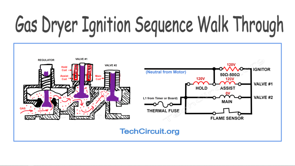
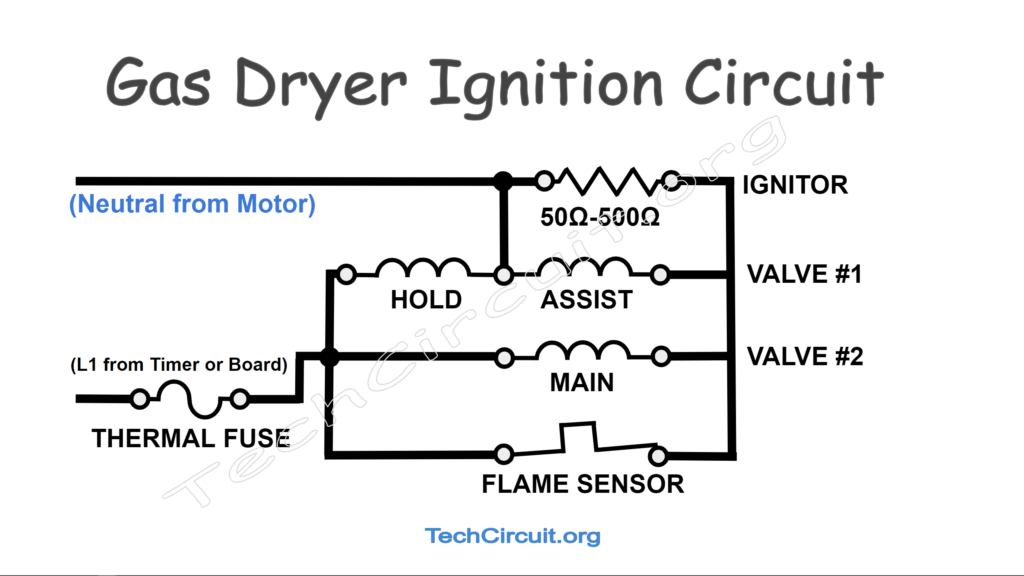
The ignition circuit consists of an ignitor, three coils, and a flame sensor. The hold and assist coils must both be energized in order to open Valve #1. Once open, it will remain so even if the assist coil is de-energized. The main coil, once energized, opens Valve #2. Once both valves are open, gas will flow. The ignitor has a much lower impedance (50 – 500 ohms) than the coils (500 – 2000 ohms) , which is key to the circuit’s operation. The flame sensor is closed until it detects enough radiant heat to switch it to an open state. Until then the main coil is “shunted” or “bypassed” by the sensor, and essentially no current passes through the coil, and no voltage can appear across it. Once the flame sensor opens, the main coil gets about 110v (some is lost across the low impedance ignitor), which opens Valve #2. Once both valves are open, gas will flow.
Step by step Ignition Sequence
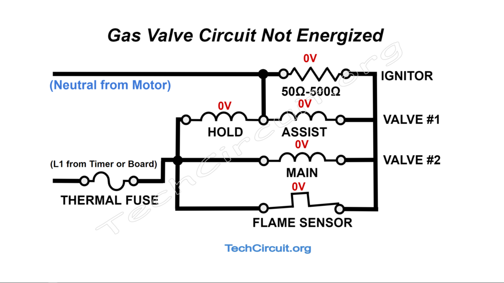
Ignition Circuit not Energized
On the basic Whirlpool made dryers with a timer, once advanced, the timer conveys 120v to the ignition circuit through the thermal devices so that it appears at the left side of the flame sensor. This may also be accomplished by a relay on a control board for the more intelligent models. Note that although the left side of the flame sensor and the left side of the hold and main coils have 120v w/r to neutral, no current flows through the circuit because neutral is not yet present on the left side of the ignitor. This will occur when the motor is not running – thereby not activating the centrifugal switch that normally passes neutral along to the ignition circuit. This means that there’s no voltage difference across the ignitor nor any voltage difference across any of the coils.
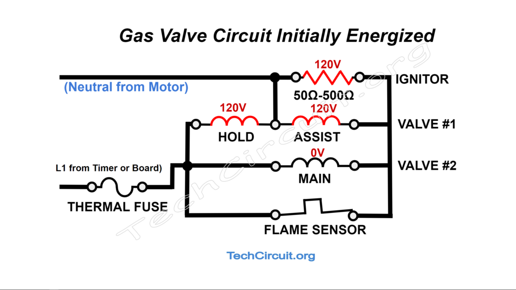
Ignition Circuit Initially Energized, Flame Sensor Closed
This state assumes that the motor is running to RPM and that neutral appears at the left side of the ignitor. This creates a voltage difference of 120v across the ignitor because the flame sensor is closed. The ignitor now glows and the flame sensor is preparing to open. This also creates voltage difference of 120v across the “hold” and assist coils, opening Valve #1, and allowing gas to reach section 1 of the gas valve assembly as depicted below. Note that the main coil is still not energized, which disallows gas to flow completely though the assembly.
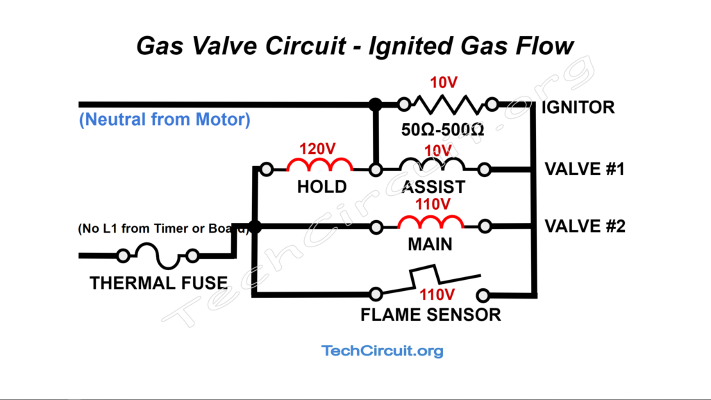
Flame Sensor Opens, Ignited Gas Flows
Once the flame sensor opens, current no longer passes through it. However, the relatively low resistance of the ignitor allows enough current to pass through it to energize the coils. In fact, most of the 120v appears across the coils, whereas about 10v is lost across the ignitor. This is called a voltage divider, where the highest resistance(or impedance if you will), gets the greatest share of the available 120v. This means that the assist coil has about 10v across it, the hold coil 120v, and the main coil 110v. This is the only state that allows gas to flow all the way through the assembly. Remember, that both the assist coil and hold coil were both energized before the flame sensor opened. The assist coil is no longer energized, but doesn’t need to be as the hold coil keeps Valve#1 open. The main coil (which was shunted prior), gets the 110v necessary to open it. This is depicted below.
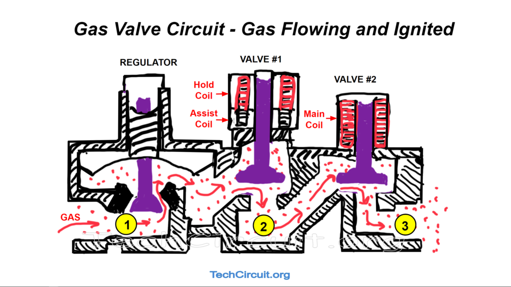
Gas Dryer Valve Assembly – Gas Flowing and Ignited
Heat Cycled Off, Ignition Circuit De-Energized
Once the heat cycles off via the cycling thermostat (or an open relay in the case of an electronically controlled dryer). The cycling thermostat is open, and there is 120v across it. This is because neutral appears at the right side of said thermostat, because no current is flowing through the ignition circuit, and resultingly, no voltage drop appears across the ignitor. The effect is the same a the previous section in this blog (ignition circuit not energized), except that neutral is present, and L1 is missing from the ignition circuit.

Failures
We’ll now describe some of the more common failures of the ignition circuit, and how to diagnose them.
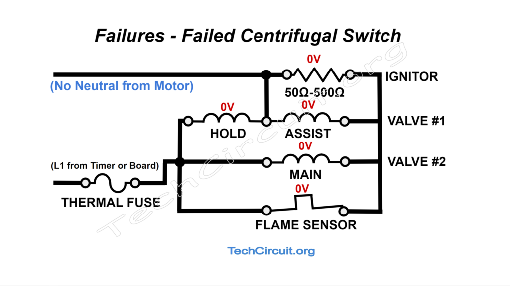
Failed Centrifugal Switch
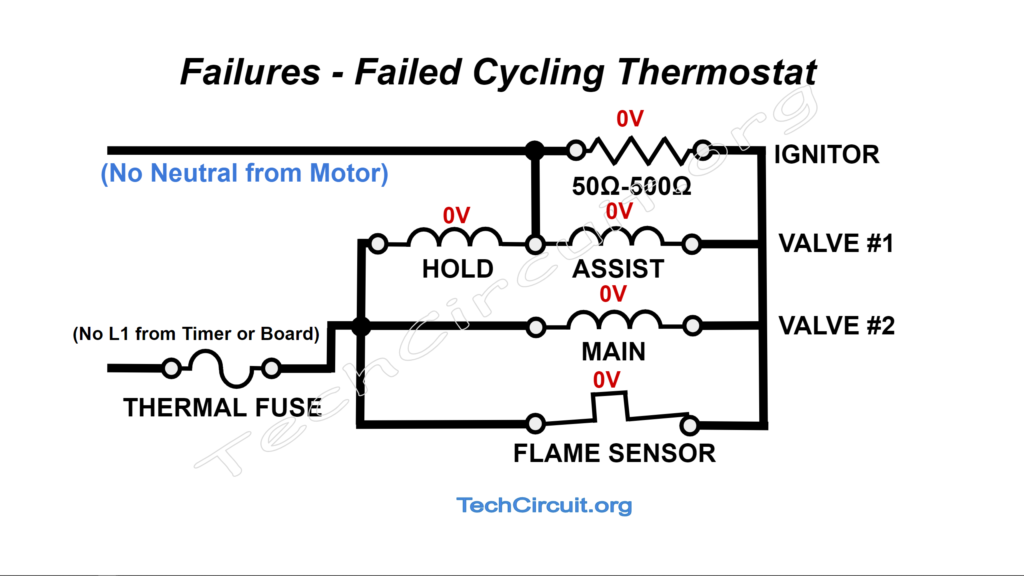
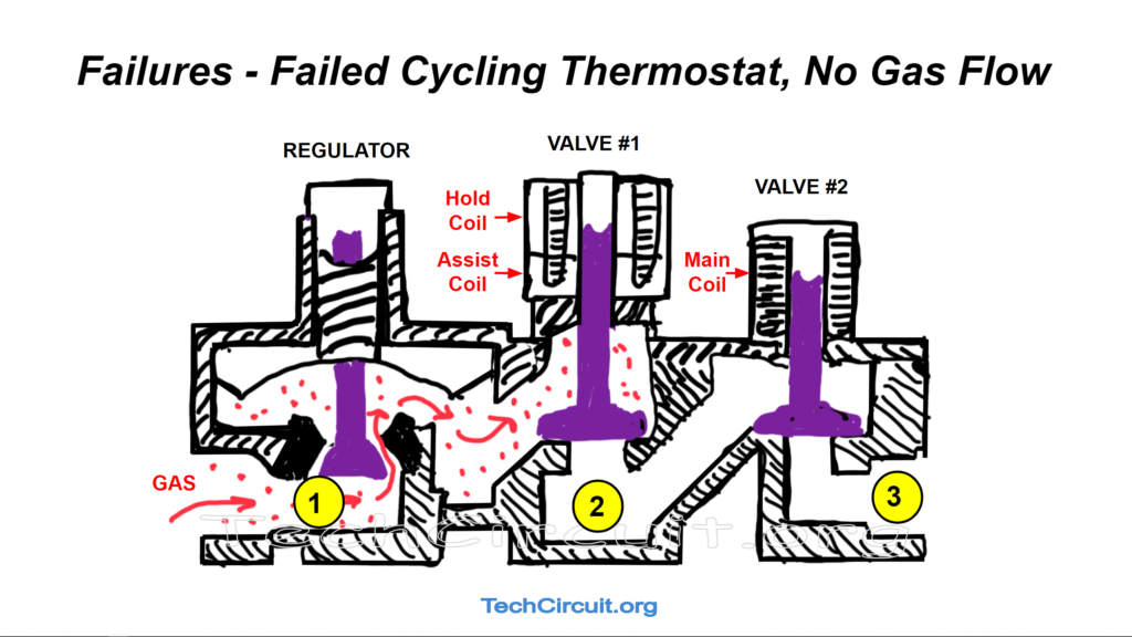
When the “heat” contacts of the motor’s centrifugal switch fail, it won’t present “neutral” potential to the ignition circuit. There is thus no return path for L1 through the circuit, and no energizing of the ignitor or solenoids, and no gas will flow (although L1 will be present at the thermal fuse and the left side of the flame sensor, main, and hold coils with respect to the house supply’s neutral. This failure state is depicted below in both the circuit, and valve assembly, along with expected voltage measurements.. The characteristic symptom is that no clicks will be heard from the gas valve assembly and gas will not flow.

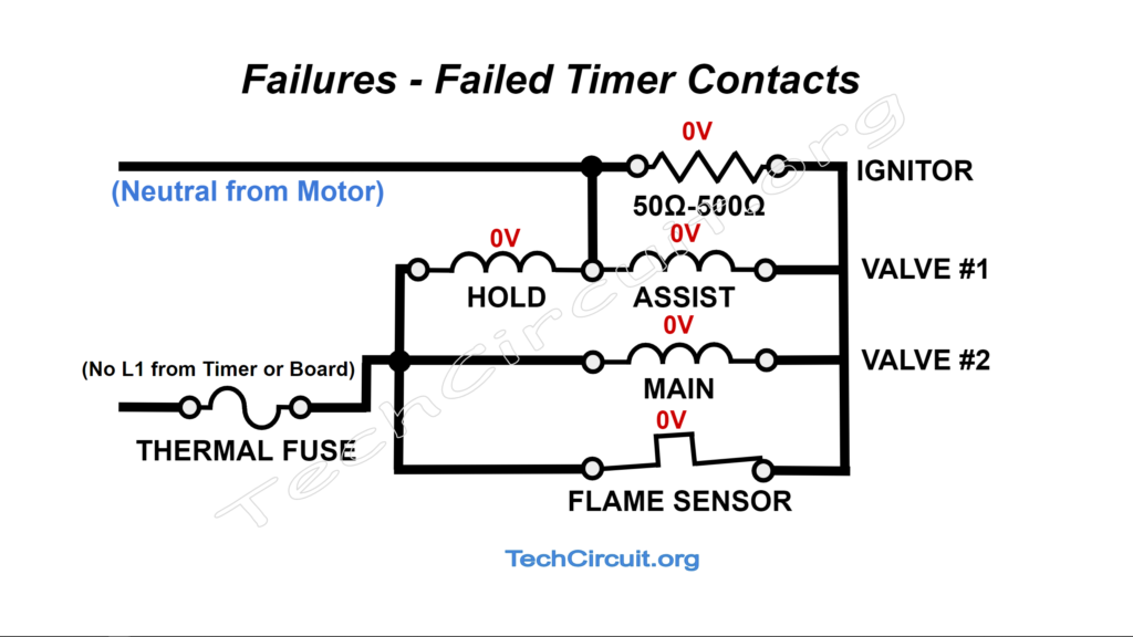
Failed Timer Contacts
If the timer fails (or control board relay doesn’t close) in such a way as to disallow L1 from reaching the ignition circuit, neither the ignitor nor the gas valve solenoids will be energized, and no activity will occur within the circuit or with the valve itself. This state is shown below in both the circuit and the valve assembly, along with expected voltage measurements.. The characteristic symptom is that one would not hear any clicks from the gas valve assembly as no valves would open, the ignitor would not glow, and no gas would flow.

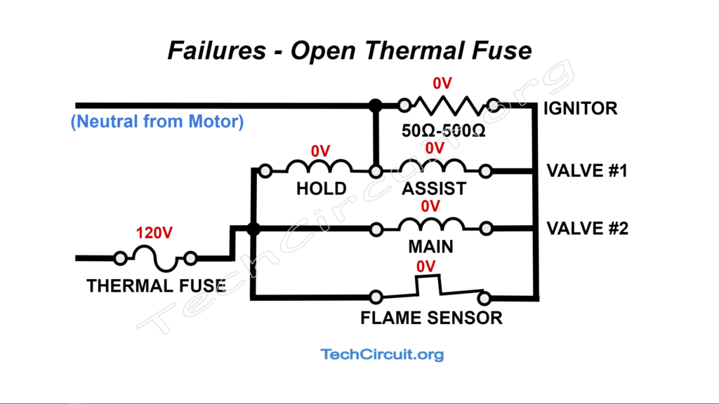
Open Thermal fuse
The thermal fuse conveys L1 to the ignition circuit, so the result will be the same as the above failure “Failed timer contacts” both electrically, and functionally, except that 120v can be measured across the thermal fuse as that is the “break” in the circuit. This is depicted below with associated expected voltage measurements. The characteristic symptom would be the same as that with the above failure “Failed timer contacts”.
Open Thermal cutoff or cycling thermoset
Both the thermal cutoff and cycling thermostat convey L1 to the ignition circuit, so the result will be the same as the above failures “Failed timer contacts”, and “Open thermal fuse”, both electrically, and functionally. This is depicted below with associated expected voltage measurements. The characteristic symptom would be the same as the above two failures “Failed timer contacts”, and “Open thermal fuse”.
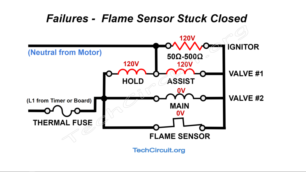
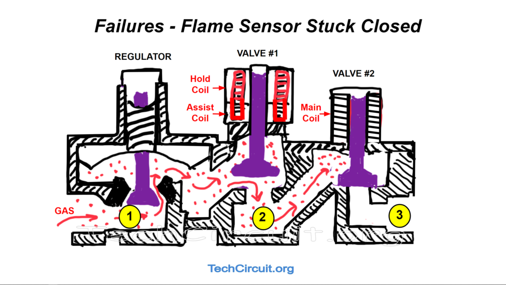
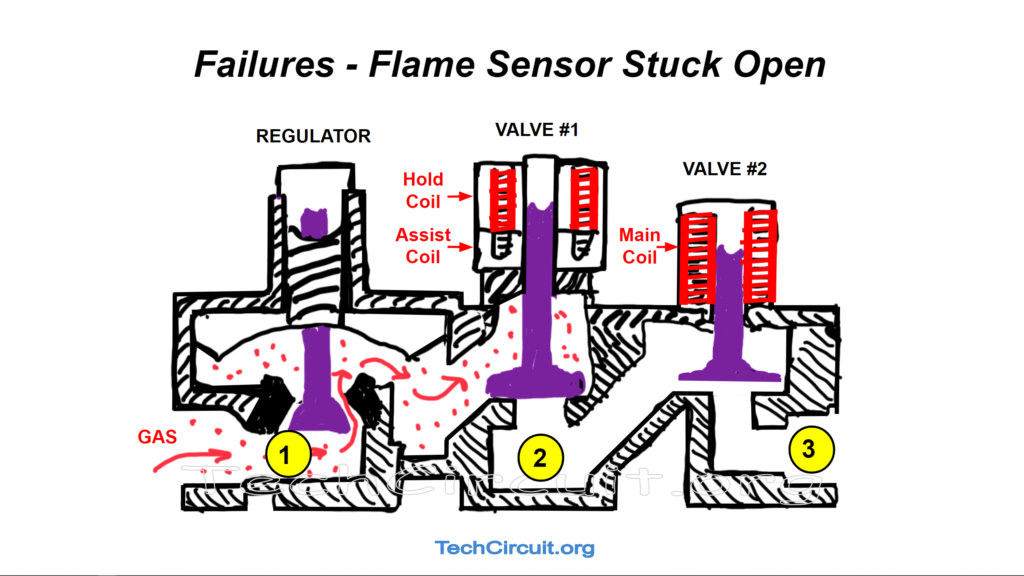
Failed Radiant Sensor (closed state)
If the radiant sensor fails in a closed state (radiant heat won’t trigger it open), the ignitor will simply glow, the hold and assist coils will be energized, Valve #1 will be open,, but the main coil will remain electrically shunted by the flame sensor and un-energized. Thus Valve #2 will stay closed and no gas will flow. This is depicted in the image below with associated expected voltage measurements. The characteristic symptom would be that one would hear Valve #1 open, the ignitor would glow and continue to glow, and no other activity would occur. No gas would flow.
Failed Radiant Sensor (open state)
If the radiant sensor fails in an open state, both the main and hold coils will be energized (and Valve #2 will open), but not the assist coil. The assist coil will only have about 10V across it Without the assist coil, Valve #1 won’t open, and gas won’t flow. This is depicted below with expected voltage measurements. The characteristic symptom is that one would hear Valve #1 open when the heat cycle is started, the ignitor wound not glow, and no other activity would occur. No gas would flow.

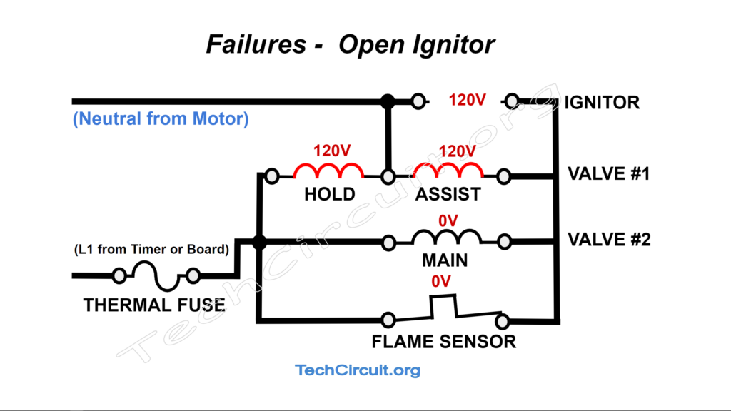
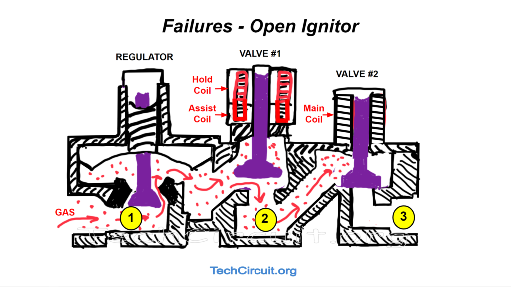
Open Ignitor
When the ignitor is open (broken, or very high resistance), it won’t glow, but the hold and assist coils will be energized and Valve #1 will open. However, The flame sensor will never open, and the mail coil is “shunted”, meaning that the flame sensor presents a short circuit across the coil and diverts all of the available current away from the main coil. Thus the main coil is not energized and Valve #2 does not open. The characteristic symptom is that when the heat cycle is started, a click will be heard as Valve #1 opens, but nothing else happens, and no gas flows.
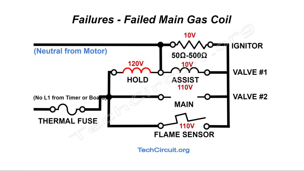
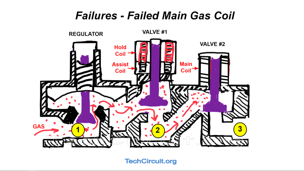
Failed Main Gas Coil
When this happens, The hold and assist coils are initially energized, Valve #1 opens, the ignitor glows, and even the flame sensor opens. However, the main coil is de-energized because no current flows through it. The result is that it does not pull Valve #2 open and no gas flows. Once the flame sensor opens, the assist coil is no longer energized, but Valve #1 is held open. This is depicted below. The characteristic symptom would by cyclical in nature in that one would hear Valve #1 open, and then the flame sensor open, then close a few seconds later, and hear it re-open after the ignitor glows to temperature again. No gas would flow. Note that solenoid failures often manifest as intermittent heat, as the coil wire opens when it warms up.
Test Your Knowledge!
Take this quiz based on the content of this article, and see how high you can score! Answers to incorrectly answered questions are provided at the end of the quiz!
Whirlpool Gas Dryer Ignition Circuit: Theory and Troubleshooting
Select the best answer for each question based on the article. Some questions may have "all of the above" or "none of the above" as possible answers.
Conclusion
The common gas valve assembly often used in Whirlpool made dryers, is a clever design that employs safety features that help protect the user by disallowing gas flow in the many envisioned failure states that could occur. It’s operational sequences may seem complicated, but are not difficult to understand after some education on the subject. Some common failures are:
- Failed centrifugal switch – neutral not presented to ignition circuit.
- No L1 being conveyed to ignition circuit (thermal fuse, thermostat, timer, relay)
- Failed Radiant Sensor (Closed)
- Failed Radiant Sensor (Open)
- Open Ignitor
- Failed Main Gas Coil
The reasons for these symptoms (as they apply to the ignition circuit), are described in detail, both electrically, and functionally within the gas valve assembly. The reader should now have a better understanding of both how the circuit and valve work, as well as what causes specific ignition related problems.
Don’t forget:
“Diverting 10 min/day of social media time towards learning something new, is 5 hours of newfound monthly knowledge.” – SM
To DONATE to the Tech Circuit – CLICK HERE
Alphabetical Links to all Tech Circuit Articles and Blogs – CLICK HERE
Links to all Tech Circuit Cheat Sheets/Field References for Appliance/HVAC Techs – CLICK HERE
For additional electrical and electronics learning material for field techs, visit the following links:
Homepage at http://www.TechCircuit.org
Facebook group at: https://www.facebook.com/groups/746823709133603
Youtube Channel: https://www.youtube.com/@TheTechCircuit