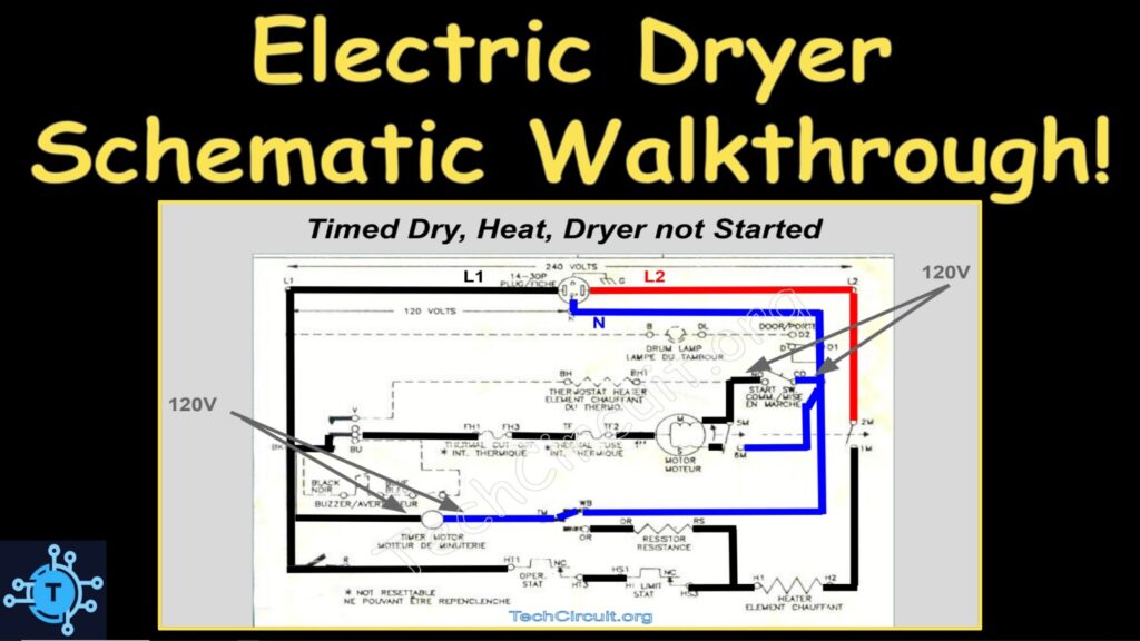
How do you read an electric dryer schematic? In this video, voltages maps overlaid on a schematic for a common Whirlpool made electric dryer. What voltages to expect for different operating scenarios and failures. You will be walked through all relevant functional states of this dryer, as well as its common failures. Within these walkthroughs, you will be shown what voltage appear at what points in the sub-circuits using a color scheme where Black is Line 1 (L1), Blue is Neutral, and red is Line 2 (L2). Through this, you will be able to readily visualize what loads are or are not energized, and what readings you should get with your multimeter when doing live tests.
Click HERE (or the picture below) for the Video or HERE to Subscribe to The Tech Circuit Video Channel.
For tons of videos on electrical and electronics diagnostics, practical electrical theory, and field-technician resources, click the picture below or this link here: https://www.youtube.com/@TheTechCircuit?sub_confirmation=1

More about the Whirlpool Electric Dryer Schematic Walkthrough
Please note that this blog is intended for Appliance Technicians familiar with safety procedures associated with live troubleshooting. Take care when performing live tests as lethal voltages are often present. Do not work on live circuits unless you are qualified to do so.
Voltage Maps
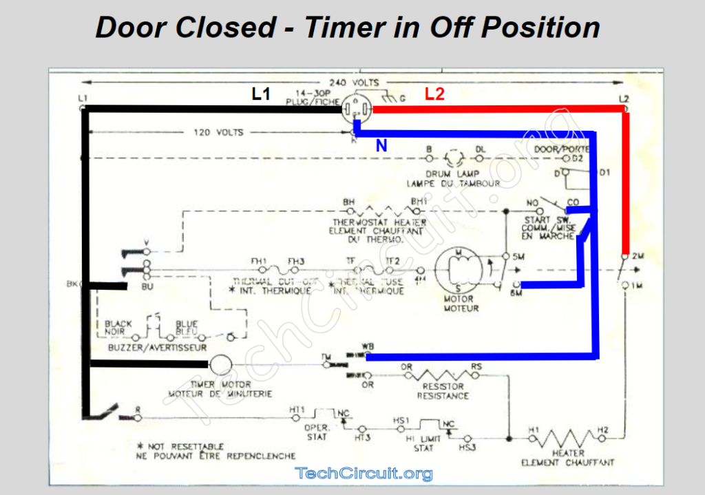
Baseline Starting Point
This video first presents to you the basic schematic diagram of the electric dryer. It then shows you a colorized voltage overlay of what the dryer when the door is closed and the timer is in the off position. This is your baseline starting point.
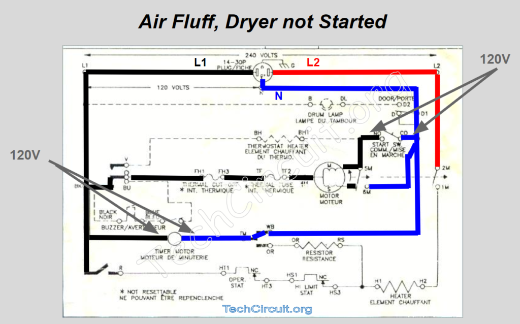
Air Fluff
It then proceeds to the timer being advanced to air fluff, which energizes the timer motor. This results in a very different voltage layout. The drive motor is as this point, ready for “start up” upon pressing of the start button.
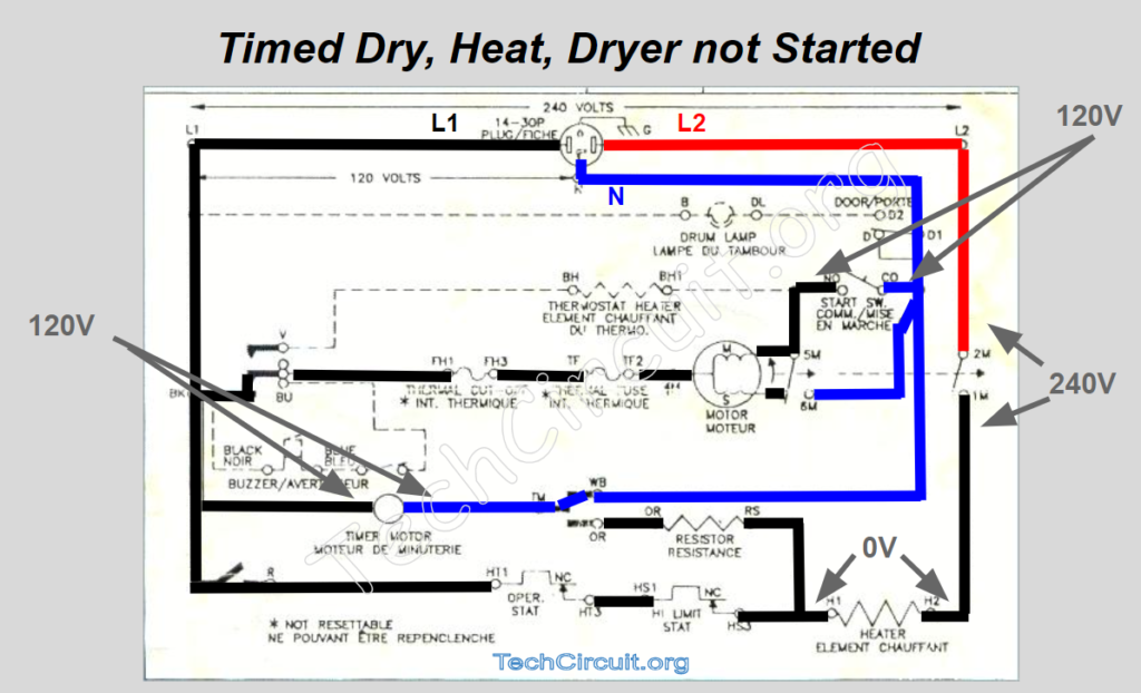
Timed Dry, Heat, Dryer Not Started
This state is very similar to air fluff in that it prepares the motor for start-up, but it also commutes L1 to the heating element. This also prepares the heating element for energization, once the motor ramps up and the centrifugal switch commutes L2 to the other side of the element.
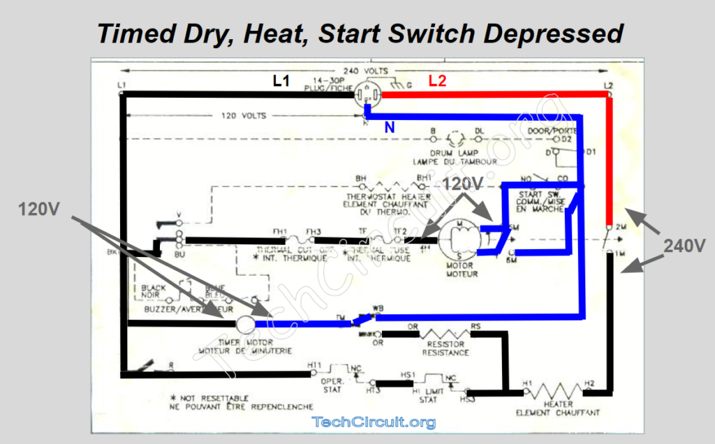
Timed Dryer, Heat, Start Switch Depressed
This is when things start happening. When the start switch is depressed, the motor’s start winding is energized, which initiates rotation of the motor. This type of motor is called a single split phase motor, where the relative inductances and resistances of the start vs. main windings, elicits a rotating magnetic field that spins the armature. Once the motor reaches a target RPM, the centrifugal switch disconnects the start winding from the circuit and leaves the main winding to sustain rotation in the direction in which it was initiated.
Next Steps
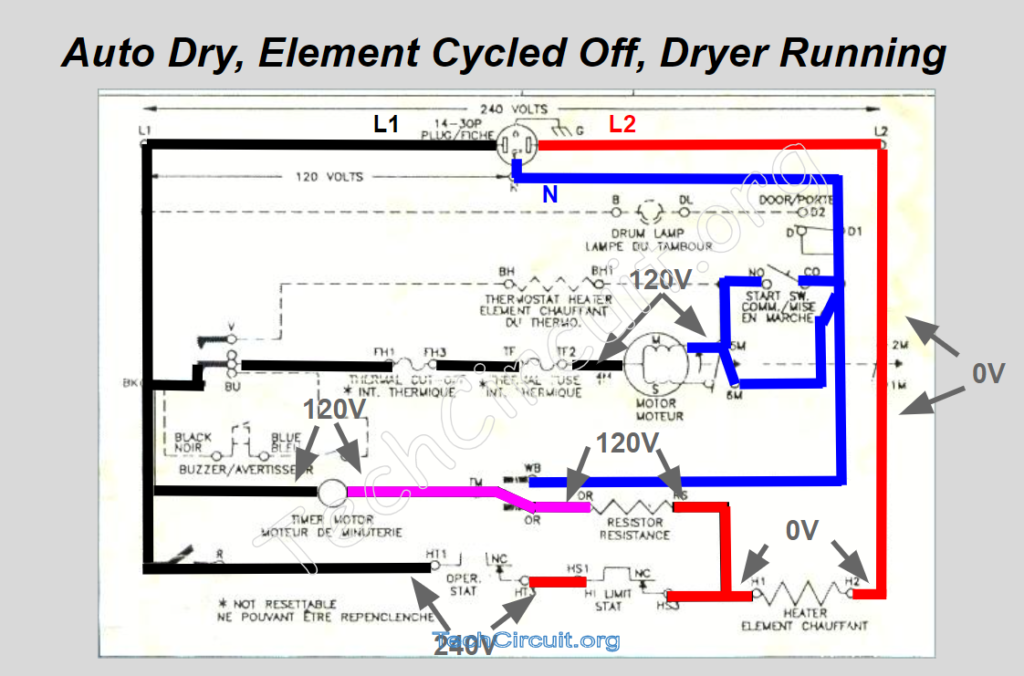
The video then moves on to the more complex functions such as auto-dry and its use of voltage dividers i.e. relative impedances to supply voltage to the timer motor through the heating element. This stuff is really interesting and enlightening for those wishing to learn about electrical theory, so be sure to watch the video here: https://youtu.be/UoJbLXcZPUs
More about The Tech Circuit
Don’t forget:
“Diverting 10 min/day of social media time towards learning something new, is 5 hours of newfound monthly knowledge.” – SM
To donate to the Tech Circuit – CLICK HERE
For additional electrical and electronics learning material for field techs, visit our homepage at http://www.TechCircuit.org
or our YouTube Channel at https://www.youtube.com/c/TheTechCircuit
or our Facebook group at https://www.facebook.com/groups/746823709133603.