In this Cheat Sheet, you’ll find most every bit of electrical information that Field Technicians need while on-site or in an academic setting. Most notable are “Electricity Basics”, “Ohm’s Law”, “Basic Circuits”, “Appliance Topologies”, “Diagnostics”, and “Formulae”. Bookmark this page for quick reference for whenever you may need to reference such information, or to just brush up on your knowledge.
This comprehensive “cheat-sheet” contains the information listed below. Click on the link to navigate to the section of your choice:
- Electricity Basics
- Ohm’s Law
- Watt’s Law
- Basic Circuits
- Voltage Sources and Failures
- Appliance Topologies
- Point to Point Diagnostics
- Terminal Blocks and Hookups
- Range Ignitor Currents
- Electric Range Element Currents, Resistances, an Wattages
- Electric Range Common Symptoms and Causes
- Room Temp Values for Common Thermistors
- Electrical Formulae
Subscribe to the Tech Circuit YouTube Channel
For hundreds of videos on electrical and electronics diagnostics, practical electrical theory, and field-technician resources, click the picture below or this link here: https://www.youtube.com/@TheTechCircuit?sub_confirmation=1

Electricity Basics
Electricity is the movement of electrons through a conductor. In appliances, this movement is harnessed to produce heat, light, or motion. Understanding basic electrical flow is key to accurate troubleshooting. Voltage is the force, or pressure, which causes current to flow. From our perspective, voltage appears, and current flows.
Ohm’s Law
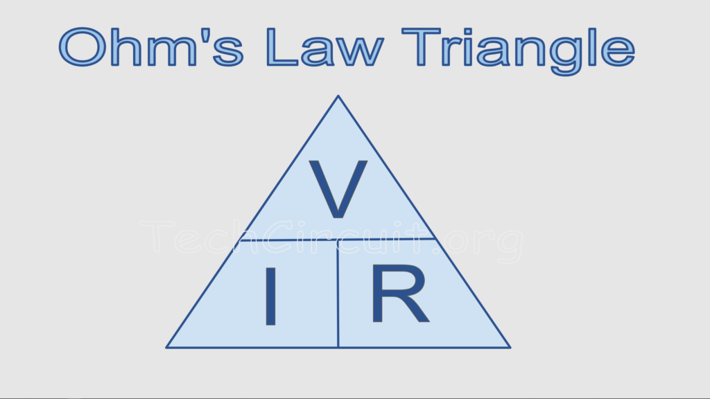
Ohm’s Law: V = I × R, R=V/I, or I=V/R
- V = Voltage (Volts)
- I = Current (Amps)
- R = Resistance (Ohms)
Use this to figure out missing values. For example, if an element draws 10A on a 120V line:
R = V ÷ I = 120 ÷ 10 = 12Ω
Watt’s Law
Watt’s Law: P = V × I, V²/R, or I² x R
- P = Power (Watts)
Useful for calculating energy use and checking component loads.
Example: 120V × 12A = 1440 Watts
Affect of Voltage on Power Output
Important in this industry – doubling the voltage across a fixed resistance load also doubles current. This has an exponential effect on power. Thus:
- Doubling voltage quadruples power
- Halving voltage drops power to 1/4th.
Basic Circuits
All circuits need a power source, a load, and a path (complete loop). Break the path and the load stops working.
Closed Circuit
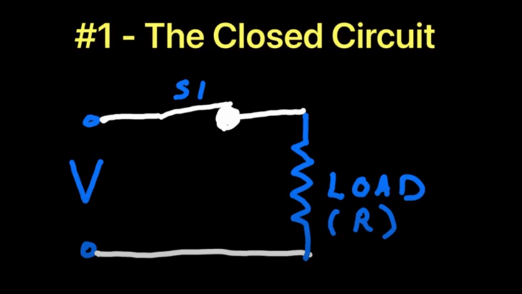
A complete path exists from hot to neutral. The load operates as intended.
Short Circuit

Current bypasses the load and goes directly to neutral or ground. Often blows fuses or trips breakers.
Open Circuit
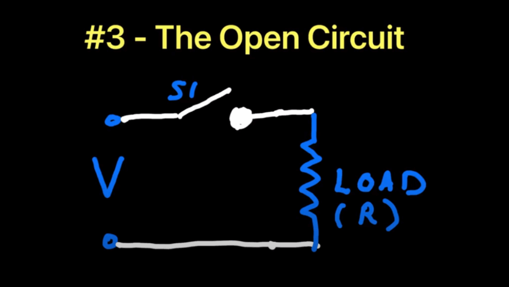
An intentional or accidental break. Could be a switch, fuse, or broken wire. No current flows.
Series Circuit

Loads are connected end to end. Current is shared across each load. One failure breaks the whole circuit.
Parallel Circuit

Each load has its own path to hot and neutral. One load can fail without affecting others. Multiple cooktop burners operating simultaneously is an example.
Voltage Sources and Failures
What is a Voltage Source?
It is your source of electromotive force (voltage). This supplies electrical pressure.
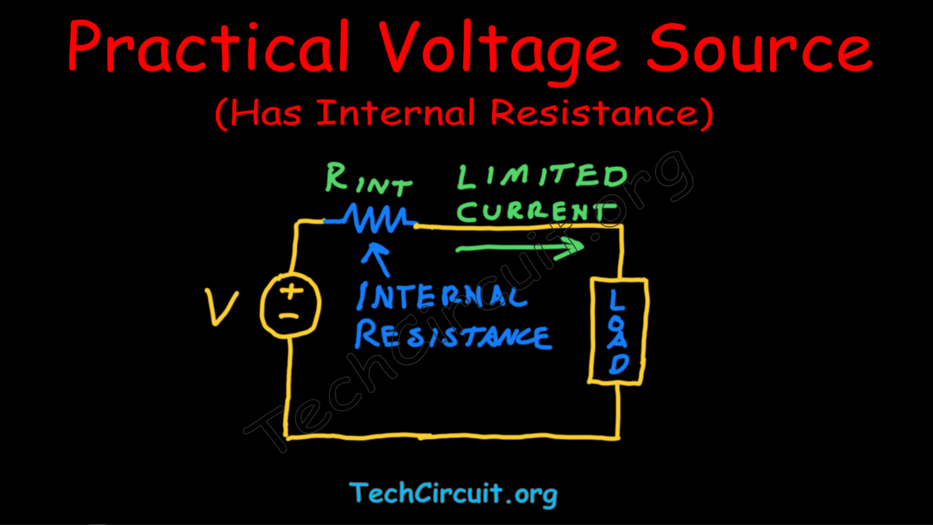
Ideal vs. Practical Voltage Source
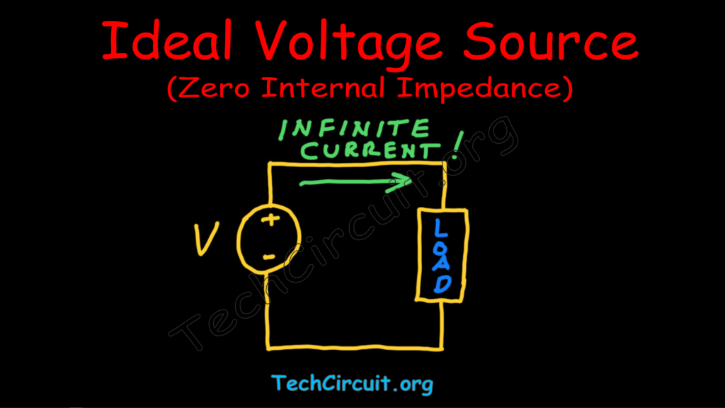
The ideal voltage source can supply any amount of current without dropping in voltage. All practical voltage sources have internal resistance or impedance. This limits the amount of current they can supply. The greater the resistance, the more the voltage drops when under load. The lower the resistance, the greater capacity it has to supply current.
Functional Voltage Source
Delivers stable voltage under an expected load. Example: 120V line shows approximately 120V when a motor is running.
Voltage Source Examples:
- 9V Battery (Weak Voltage Source)
- Internal Resistance – about 5 ohms
- Maintains 80% of its voltage at 0.36A draw.
- 120V Residential Outlet (Fairly Strong Voltage Source)
- Internal Resistance – about 0.5 ohms
- Maintains 80% of its voltage at 48A draw (or until breaker trips).
- 12V Car Battery (Extremely Strong Voltage Source)
- Internal Resistance – about 0.02 ohms
- Maintains 80% of its voltage at 120A draw.
Compromised Voltage Source
Voltage may read normal with no load but drops under load due to an unexpected internal (upstream) resistance or impedance. A LoZ meter can help identify this condition. Look for weak breakers, burnt terminals, loose upstream connections.
Compromised Neutral
Voltage may be present with a standard multimeter but drops under load or with a LoZ meter. Also can be caused by loose upstream connections on the neutral line.
Appliance Topology Basics
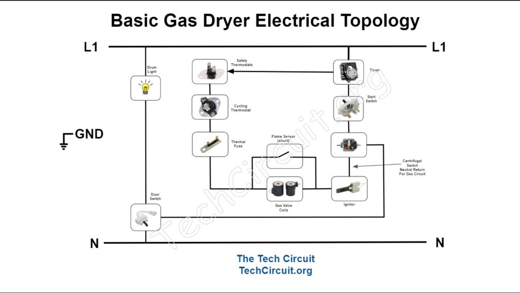
120v Appliance Topology Overview
A basic gas dryer runs on 120v, where L1 (hot) references N (neutral) to power the motor, timer, and ignition circuit.
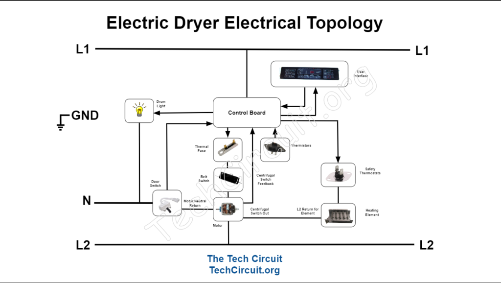
240v Appliance Topology Overview
A basic 240v dryer runs on both 120v and 240v, utilizing the 120v to power the timer (if 120v timer) or control board, referenced from L1 to Neutral. 240v is used to power the heating element, referenced from L1 to L2.
Point to Point Voltage Testing Diagnostics
Point to point diagnostics utilizes “voltage differences” to granularly ascertain a circuit’s status. This troubleshooting method is most useful for single-load circuits, which are most often relevant to appliance failures.
120v Point to Point Circuit Testing with Multimeter
Identify your “subject load” – the load you wish to investigate (motor, ignition circuit, etc.), and locate the circuit associated with that load. Set your meter on an appropriate mode for measuring 120v AC. Connect one lead to neutral (not ground). Energize the circuit. With the other multimeter lead, start at neutral and test each point in the circuit until you read 120v. The component just prior to that point is open and should be further investigated.
120v Point to Point Circuit Testing with Voltage Pen
The same method applies for voltage pen testing as with a multimeter, except that you don’t need a reference point. The pen will “trigger” on a perceived hot (120v). Start at neutral and go point-by-point until the pen triggers. The component just prior to that is open and should be further investigated.
240v Point to Point Diagnostic Testing
240v diagnostics does not reference neutral or ground. They are not part of the 240v circuit. Identify your “subject load” – the load you wish to investigate (heating element), and locate the circuit associated with that load. Set your meter on an appropriate mode for measuring 120v AC. Connect one lead of your meter to L1. Energize the circuit. Starting at L1, go point by point with the other lead until you read 240v. The component just prior to that point is open and should be further investigated.
Terminal Blocks and Hookups
Electrical and mechanical intermediary used to transfer voltage to an appliance. Common failure point. Overheated connections often present when loose and subject to high currents.
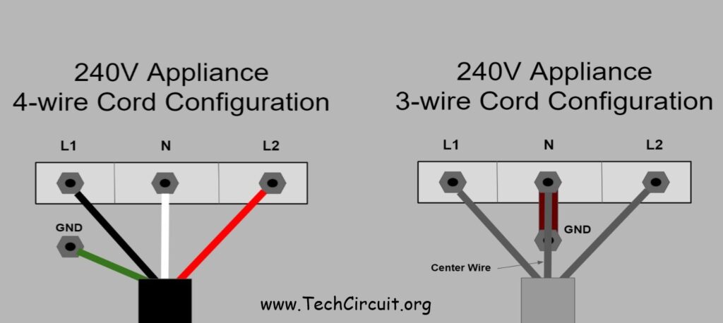
3 Wire Cord Hookup
Older style: L1, L2, and Neutral/Ground shared
Middle terminal is neutral, outer terminals are hots.
Chassis is bonded to neutral using a strap or wire.
4 Wire Cord Hookup
Modern standard: Separate ground and neutral
L1 and L2 (outer terminals), Neutral (center), Ground (green screw or chassis lug)
Remove neutral-ground strap when using 4-wire.
Why Ground and Neutral Should be Separated
Neutral carries return current. Ground is only for faults.
If bonded incorrectly, the chassis can carry current during normal operation, which is a shock hazard, and can damage control boards in the event of a short circuit.
Terminal Block Failures and Symptoms

Signs: Burn marks, melted plastic, intermittent power, no heat.
Often caused by loose screws, high resistance connections, or overload.
Always inspect during power complaints.
Gas Range Ignitor Currents
- Standard round ignitor – 2.3 – 2.6 amps
- Standard square ignitor – 3.2 – 3.6 amps
Electric Range Element Typical Resistances, Currents, and Wattages
- Oven Sensor
- 1080 Ohms @ Room Temp
- Bake Element
- 24 Ohms
- 10 Amps
- 2400 W
- Broil Element
- 18 Ohms
- 14 Amps
- 3300 W
- 8″ Cooktop Coil Burner
- 28 Ohms
- 7.5 Amps
- 2200 W
- 6″ Cooktop Coil Burner
- 40 Ohms
- 6 Amps
- 1400 W
Electric Range Common Symptoms and Causes
Missing or Compromised L1
- Display lights up only when cooktop burner is turned on
- No display or functioning electronics if burners off
- No bake or broil
- Burners don’t work
Missing or Compromised L2
- Display and electronic controls work
- 120v warmers work
- No bake or broil
- 240v cooktop burners do not work
Missing or Compromised Neutral
- No display or electronic controls
- Irregular voltage readings between L1 w/r to neutral and L2 w/r to neutral
- Bake and broil won’t work if using an electronic control
- Bake and broil will work if using mechanical controls
- 240v cooktop burners work
Reversed L1 and Neutral
- Display and controls work
- Bake and broil only get warm
- Cooktop burners only get warm
- Note: All 240v burners and elements will only get 120v and will only emit 1/4 of the heat per Joule’s law.
Reversed L2 and Neutral
- Display and controls likely damaged (exposed to 240v instead of 120v)
- 240v cooktop burners only get warm
- Bake and broil won’t work if powered by electronic controls
- Bake and broil will work if mechanical controls used, but will only get warm
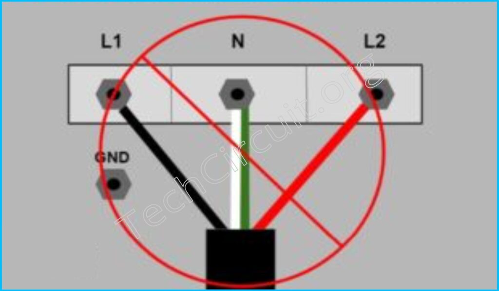
Reversed L1 and L2
No symptoms or issues
Room-Temp Values for Common Thermistors
Approximate Values
- Standard Range Sensor – 1080 Ω
- Whirlpool Dryer Exhaust Thermistor (8577274) – 12500 Ω
- Whirlpool Dryer Inlet Thermistor (8577891) – 62000 Ω
- Samsung Dryer Exhaust Thermistor (DC32-00007A) – 11900 Ω
- LG Dryer Thermistor (6323EL2001B) – 11700 Ω
- GE Dishwasher Flood Switch Thermistor (WD21X10519) – 12000 Ω
- GE Refrigerator Thermistor (WR55X10025) – 6000 Ω
- Whirlpool Refrigerator Thermistor (W1020385) – 3217 Ω
- Whirlpool Refrigerator Thermistor (W10316760) – 3200 Ω
- Frigidaire Refrigerator Thermistor (240597203) – 11878 Ω
- Whirlpool Washer Tub Thermistor (W10467289) – 11000 Ω
- LG Refrigerator Thermistor (6615JB2002R) – 12700 Ω
Electrical Formulae Sheet for Appliance Technicians
🔹 Ohm’s Law
V = I × R
I = V / R
R = V / I
Example: If I = 2 A and R = 5 Ω → V = 2 × 5 = 10 V
🔹 Watt’s and Joule’s Law
P = V × I
P = I2 × R
P = V2 / R
Example: If V = 120 V and I = 2 A → P = 120 × 2 = 240 W
🔹 Equivalent Resistance – Series
Rtotal = R1 + R2 + R3 + …
Example: R1 = 4 Ω, R2 = 6 Ω → Rtotal = 10 Ω
🔹 Equivalent Resistance – Parallel
1 / Rtotal = 1 / R1 + 1 / R2 + …
For two resistors:
Rtotal = (R1 × R2) / (R1 + R2)
Example: R1 = 6 Ω, R2 = 3 Ω → Rtotal = (6×3)/(6+3) = 2 Ω
🔹 Capacitors in Parallel
Ctotal = C1 + C2 + C3 + …
Voltage is the same across each capacitor.
Example: C1 = 10µF, C2 = 5µF → Ctotal = 15µF
🔹 Capacitors in Series
1 / Ctotal = 1 / C1 + 1 / C2 + …
V1 = Q / C1, V2 = Q / C2
Example: C1 = 10µF, C2 = 5µF → 1/Ctotal = 1/10 + 1/5 = 0.3 → Ctotal ≈ 3.33µF
🔹 Voltage Divider
Vout = Vin × (R2 / (R1 + R2))
(Vout is across R2)
Example: Vin = 12V, R1 = 2kΩ, R2 = 1kΩ → Vout = 12 × (1 / 3) = 4V
🔹 Capacitor Discharge Time
V(t) = V0 × e−t / RC
To discharge to 5%: t ≈ 3RC | To 1%: t ≈ 5RC
Example: R = 1kΩ, C = 100µF → 3RC = 3 × 1000 × 0.0001 = 0.3 s to ~5%
🔹 RMS vs Peak Voltage
VRMS = Vpeak / √2 ≈ 0.707 × Vpeak
Vpeak = √2 × VRMS ≈ 1.414 × VRMS
Example: Vpeak = 170V → VRMS ≈ 170 / √2 ≈ 120V
🔹 Capacitive Reactance
XC = 1 / (2πfC)
Where XC is in ohms, f in Hz, C in farads
Example: f = 60Hz, C = 10µF → XC = 1 / (2 × π × 60 × 0.00001) ≈ 265 Ω
🔹 Inductive Reactance
XL = 2πfL
Where XL is in ohms, f in Hz, L in henries
Example: f = 60Hz, L = 100mH → XL = 2 × π × 60 × 0.1 ≈ 37.7 Ω
🔹 Impedance (from Resistance and Reactance)
Z = √(R2 + X2)
Where R = resistance (Ω), X = reactance (Ω), Z = impedance (Ω)
Example: R = 6Ω, X = 8Ω → Z = √(36 + 64) = √100 = 10Ω
Disclaimer:
THIS BLOG IS INTENDED FOR APPLIANCE TECHNICIANS ONLY. ALWAYS USE APPROPRIATE SAFETY PRECAUTIONS WHEN WORKING WITH ELECTRICITY. THIS BLOG IS FOR INFORMATIONAL PURPOSES ONLY. IF YOU CHOOSE TO UTILIZE THE CONCEPTS IN THIS BLOG, YOU DO SO AT YOUR OWN RISK. THE AUTHER ASSUMES NO RESPONSIBILITY OR LIABLIITY FOR ANY ERRORS OR OMISSIONS IN THE CONTENT OF THE BLOG.
Don’t forget:
“Diverting 10 min/day of social media time towards learning something new, is 5 hours of newfound monthly knowledge.” – SM
To DONATE to the Tech Circuit – CLICK HERE
Alphabetical Links to all Tech Circuit Articles and Blogs – CLICK HERE
Links to all Tech Circuit Cheat Sheets/Field References for Appliance/HVAC Techs – CLICK HERE
For additional electrical and electronics learning material for field techs, visit the following links:
Homepage at http://www.TechCircuit.org
Facebook group at: https://www.facebook.com/groups/746823709133603
Youtube Channel: https://www.youtube.com/@TheTechCircuit
For additional electrical and electronics learning material for field techs, visit our homepage at http://www.TechCircuit.org or our Facebook group at https://www.facebook.com/groups/746823709133603.
TC