Infinite Switch Detailed Operation
On electric ranges, the common infinite switch (or simmerstat) uses duty cycle manipulation similar to Pulse Width Modulation (PWM) to control the amount of power delivered to a cooktop burner ¹.
In general, PWM refers to controlling average power by rapidly switching a voltage on and off at a controlled duty cycle. While PWM is commonly associated with DC systems and electronics, the concept of duty-cycle control can apply to AC systems as well. The infinite switch achieves a similar result, but by thermal and mechanical means rather than semiconductor switching.
*To DONATE to the Tech Circuit – CLICK HERE*
*CLICK HERE FOR THE FREE ELECTRICITY MICRO-COURSE FOR APPLIANCE TECHNICIANS*
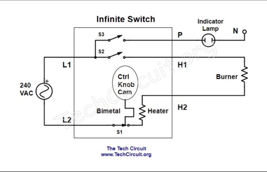
For an infinite switch, the modulating signal is the on/off action of the internal bimetal strip (as determined by the knob position and the cam’s pressure against the strip) and the carrier wave is the 240VAC sine wave at 60Hz. This strip is heated either by a small internal heater or by load current flowing through the switch, depending on the specific design. As the strip heats, it bends and opens S1; as it cools, it closes S1 again. Thus the modulating mechanism is the asymmetrical thermal expansion and contraction of the bimetal strip, with the underlying agent being the current through the circuit.
The figure below depicts a common infinite switch’s internal circuit.
Be sure to subscribe to our Youtube Channel!
For tons of videos on electrical and electronics diagnostics, practical electrical theory, and field-technician resources, click the picture below or this link here: https://www.youtube.com/@TheTechCircuit?sub_confirmation=1

Operational walk-through
When the knob is turned on, S2 and S3 close – so that L1 appears at the P and H1 terminals on the right of the infinite switch as in Figure 1. This turns on the indicator lamp and provides the potential for one side of the burner. L2 is passed through S1, but whether S1 is closed or not depends on the knob’s setting. The bimetal strip consists of two dissimilar metals that expand and contract at different rates when heated by the proximate heater resistor. When cooled, the strip closes S1. When heated, S1 is re-opened. The more force exerted against the strip by the knob cam, the longer S1 remains closed before thermal expansion overcomes the cam pressure. This is how S1 is modulated so that a variable amount of power is delivered to the load.
The infinite switch’s duty cycle determines how much power is delivered to the load by varying the percentage of time that the voltage is turned on within each time period. The time period and thus frequency of the modulation in an infinite switch is variable (unlike traditional PWM applications – such as motor control and LED lighting), and determined by knob controlled cam that presses against the bi-metal strip. Increasing cam force increases the percentage of time S1 remains closed during each heating cycle (higher duty cycle). The overall cycle period is primarily determined by the thermal characteristics of the bimetal and internal heater and does not change as dramatically as the duty cycle itself. The following oscilloscope-like images show the waveforms for different heat settings.
The figure below shows the pulsed waveform for an infinite switch set on low and minimal force exerted by the cam.

The figure below shows the pulsed waveform waveform for an infinite switch set on medium and moderate force exerted by the cam.

The figure below shows the pulsed waveform waveform for an infinite switch set on medium-high and moderately high force exerted by the cam.

Finally, the figure below shows the waveform for an infinite switch set on high or 100% duty cycle with S1 forced closed by the cam.

In the preceding figures, the duty cycle determines the percentage of power delivered to the load. Since full line voltage is applied during the on-time, average power delivered to a resistive load is proportional to duty cycle. Thus a 50% duty cycle results in approximately 50% of full rated heating power.
The reason for using duty cycle control on a stovetop burner is the same as for LED lighting and motor control. There is minimal wasted power when controlling a load by fully opening and closing a switch, because an ideal closed switch has very low resistance and an open switch carries no current. This makes time-proportioning far more efficient than using a large series resistor to reduce voltage. That is because a switch (ideally) has almost no resistance or voltage drop (and thus no power dissipation). Alternatively, simply using a resistor to drop the voltage would certainly reduce power at the load – but would dissipate a lot of wasted heat. In the case of a cooktop burner, the power reduction resistor would have to be huge and would dissipate almost as much heat as the burner itself.
How Can an Infinite Switch Behave Like PWM?
Those familiar with electronic PWM might find it unusual that an infinite switch cycles much slower than the 60 Hz AC waveform it controls. In electronic systems, PWM switching frequencies are typically very high, often thousands of times per second. The infinite switch, however, does not reshape individual AC cycles. Instead, it allows full 60 Hz sine waves to pass for a controlled percentage of time.
For a purely resistive load, such as a cooktop heating element, 240 V RMS AC delivers the same heating power as 240 V DC of equal magnitude. The element responds to average power, not instantaneous waveform shape. Because the heating element has significant thermal mass, its temperature changes slowly relative to the switching cycle, which smooths the on/off cycling into steady heat output.
For example:
If you connect 240 V DC to a 24 Ω burner:
- Current = 10 A
- Power = 2400 W
If you apply 240 V DC using 50% duty-cycle PWM, the average delivered power becomes 1200 W.
The same is true with 240 V RMS AC driving a resistive element. If an infinite switch allows full AC voltage to pass 50% of the time, the average power delivered to the burner is approximately 1200 W.
Although the mechanism is thermal and mechanical rather than electronic, the resulting effect — controlling average power by varying on-time — is functionally equivalent to PWM for resistive loads.
You’ll even find a Wikipedia entry that compares the infinite switch’s operation to that of PWM here.
Test Your Knowledge of this Content!
Understanding Infinite Switches
Select the best answer for each question.
Don’t forget:
“Diverting 10 min/day of social media time towards learning something new, is 5 hours of newfound monthly knowledge.” – SM
To DONATE to the Tech Circuit – CLICK HERE
Alphabetical Links to all Tech Circuit Articles and Blogs – CLICK HERE
Links to all Tech Circuit Cheat Sheets/Field References for Appliance/HVAC Techs – CLICK HERE
For additional electrical and electronics learning material for field techs, visit our homepage at http://www.TechCircuit.org or our Facebook group at https://www.facebook.com/groups/746823709133603.
References
————————————————————————————————————
1. Pulse-width Modulation, Wikipedia, Power Delivery, Paragraph 7 – Simmerstat, https://en.wikipedia.org/wiki/Pulse-width_modulation
————————————————————————————————————
We are a participant in the Amazon Services LLC Associates Program, an affiliate advertising program designed to provide a means for us to earn fees by linking to Amazon.com and affiliated sites.