Introduction
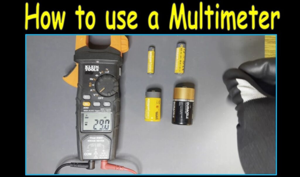
In this article, I show the very basics of multimeter usage using both a Fluke and a Klein multimeter. You’ll learn to effectively use the multimeter to test AC voltage, DC voltage, resistance, AC and DC current, as well as accurately measure temperature. At the end of this article, I’ll give you the resources to better understand some of the advanced features of multimeters—and even how to purchase some multimeters using this demonstration.
Quick Safety Note
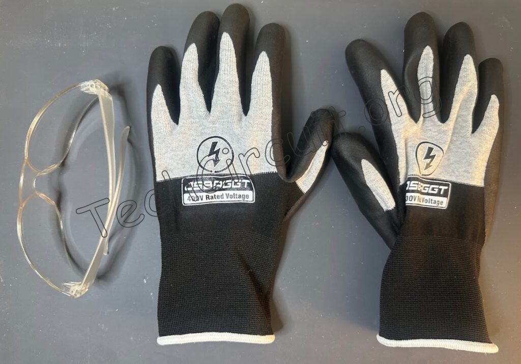
Always wear safety glasses and appropriate gloves when using a multimeter. This article is for educational purposes. I’m showing you how I do things in the field, but it is not a universal fix. Electricity is dangerous. If you’re not 100% sure, stop and call a professional. Follow your local codes, use common sense, and stay safe. You’re responsible for your own work.
Disconnect your leads before turning the dial on your multimeter. The meters in this article are auto-ranging. If yours isn’t, always set the range higher than what you expect. Never test anything beyond your meter’s limits.
Subscribe to Our Youtube Channel
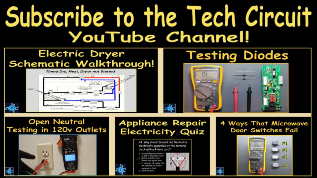
For more practical electrical theory and educational content for field technicians, click HERE, or the picture below, to subscribe to our YouTube Channel.
Measuring AC Voltage
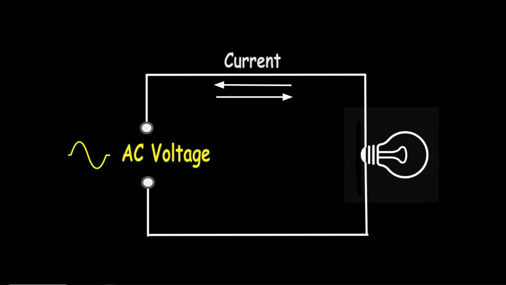
AC, or alternating current voltage, is a type of electrical voltage that oscillates—in other words, the polarity and magnitude continuously change over time. This means the current alternates direction, flowing back and forth instead of just one way like DC.
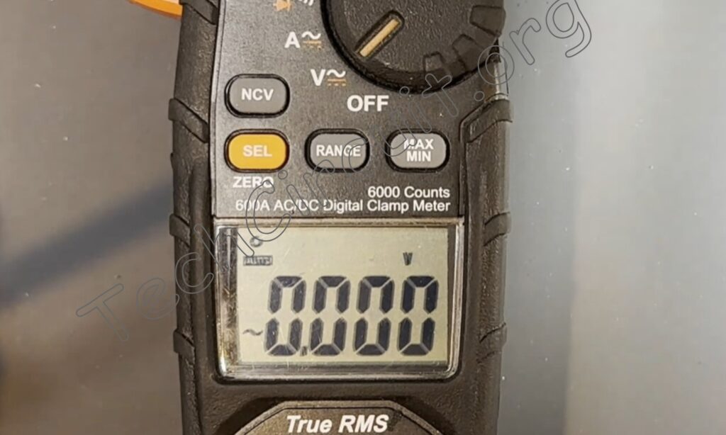
To measure AC voltage, simply turn the dial to this position here where the “V” is. On this meter, voltage defaults to AC as designated by the symbol here.
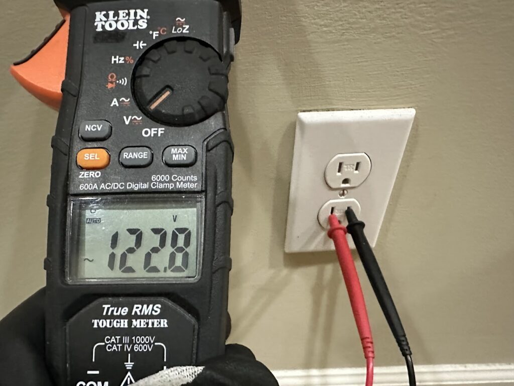
Here, you can see the Klein meter measuring the AC voltage of a 120-volt electrical outlet. A reading greater than 120 volts is not unusual, as most utility service voltages do not read exactly what they’re specified for—but usually within 5%.
Measuring DC Voltage
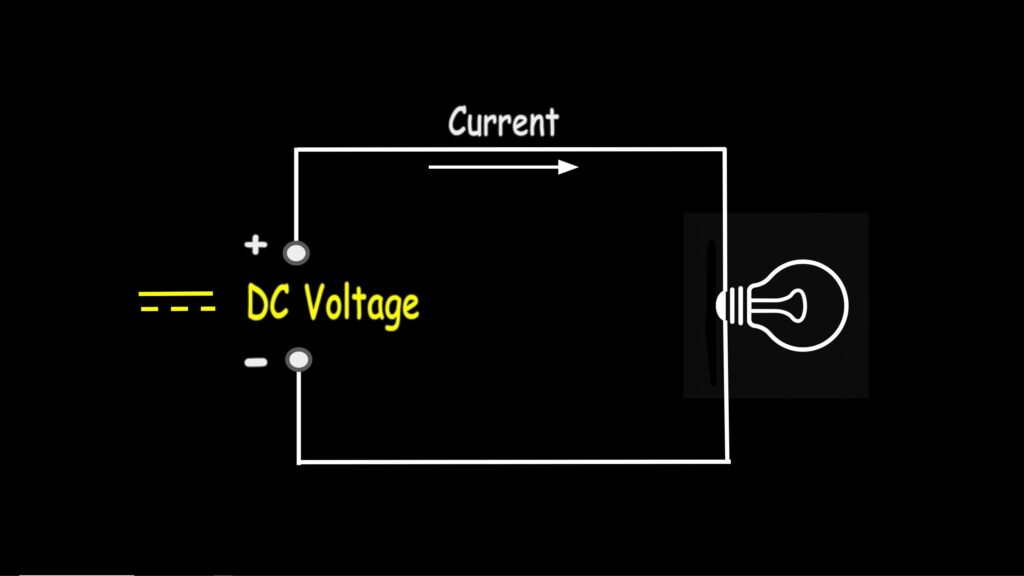
DC, or direct current voltage, is a type of electrical voltage where the polarity and magnitude remain constant over time. In simple terms, the voltage stays the same, and current flows in only one direction—from positive to negative. This is the type of voltage you would typically measure from batteries, DC power supplies, and even solar panels.
To measure DC voltage, simply turn the dial to this position here where the “V” is, and press the orange select button (if you’re using this meter) until you see the symbol for DC—which is this double line here.
We’ll measure the voltage of a 9-volt battery. The red lead goes on the positive terminal here, and the black lead on the negative terminal here. This battery has a voltage of greater than 9 volts, which means that the battery is good and likely brand new. Any reading less than 9 volts would mean the battery is likely worn out or that it sat on the shelf too long.
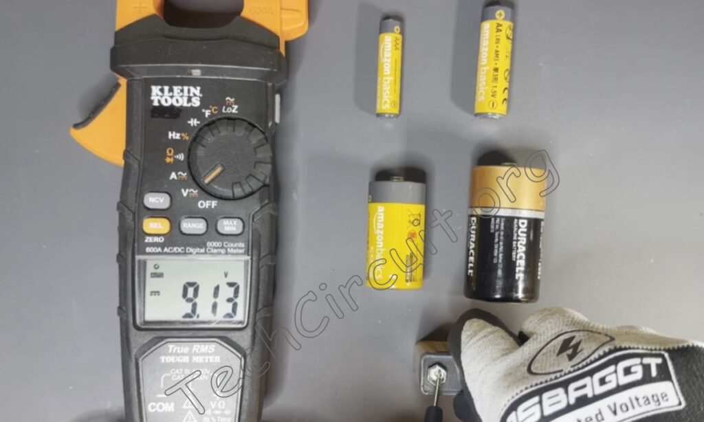
Of course, you can also use a multimeter to measure AA, AAA, D, and C cells—all of which should read 1.5 volts or better. If less, they’re probably no good. To measure such batteries, the red lead goes on the pointed tip, and the negative lead on the flat side like this. This AA battery is good because it measures greater than 1.5 volts.
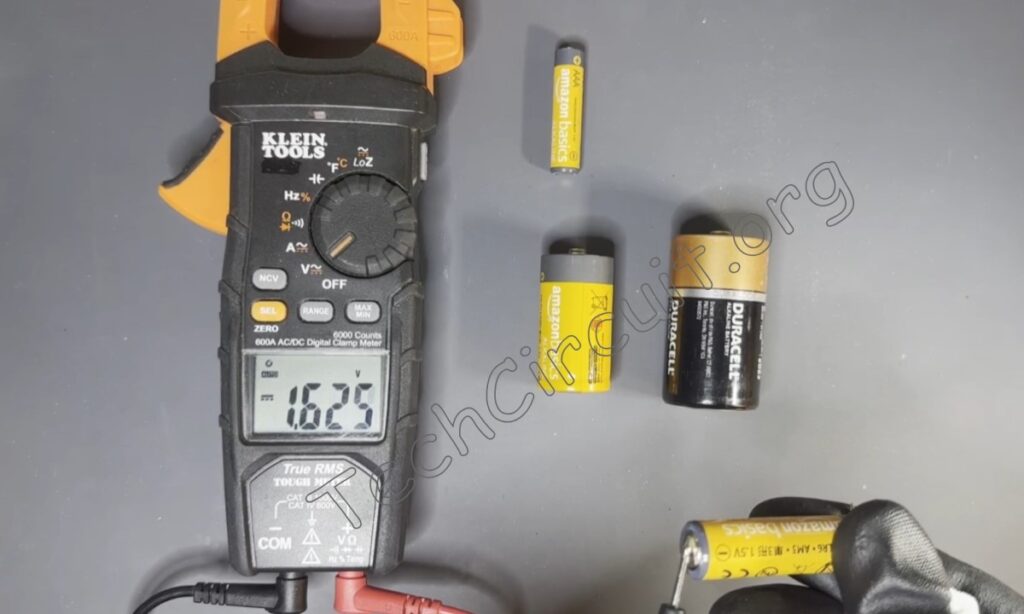
As a general rule, good healthy batteries will measure a bit greater than their rated voltage.
How to Purchase the Meters in this Article
I highly recommend either the Klein or Fluke meters in this article, depending on your needs. Here is a link to the Klein Meter (HERE).
Here is a link to the Fluke Meter (HERE).
Measuring Resistance
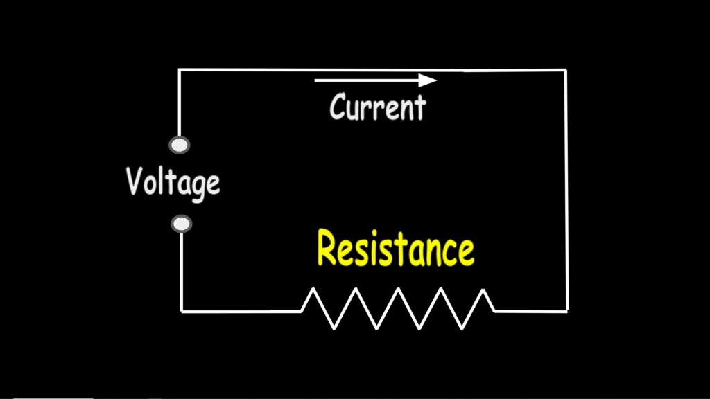
Resistance is simply the opposition to current flow, and it’s measured in ohms.
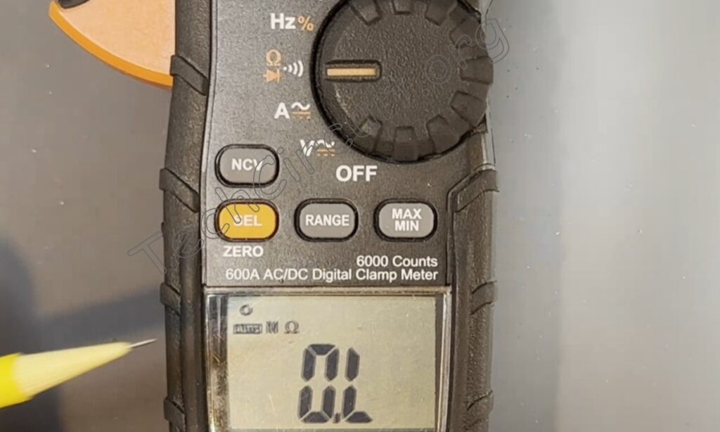
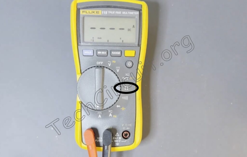
To measure resistance, simply turn the dial to this setting here. Then, for this meter, press the orange select button until the omega symbol appears. This meter will then be in resistance measurement mode.
Some meters, like the Fluke, don’t require you to press the select button—you just turn the dial to the omega symbol for ohms.
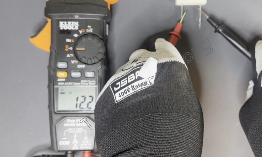
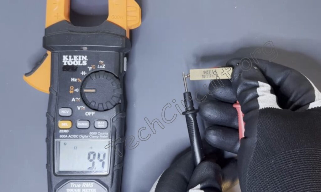
Back to the Klein meter: connect your leads across the resistor under test, and the meter will show the value of the resistor in ohms. As shown here, this is a 12-ohm resistor being measured by itself.
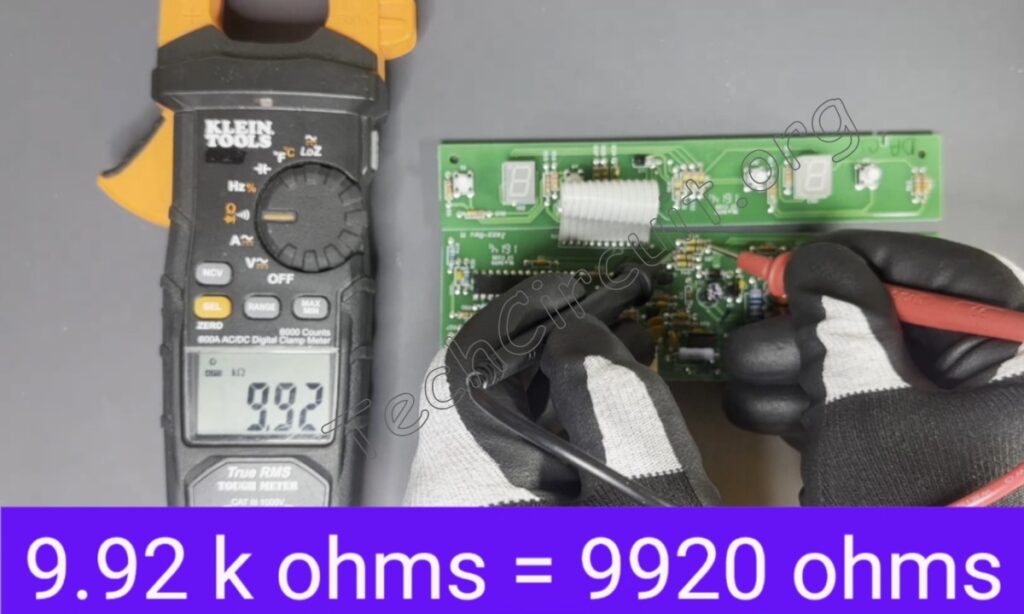
This is a 10,000-ohm resistor being measured on a circuit board.
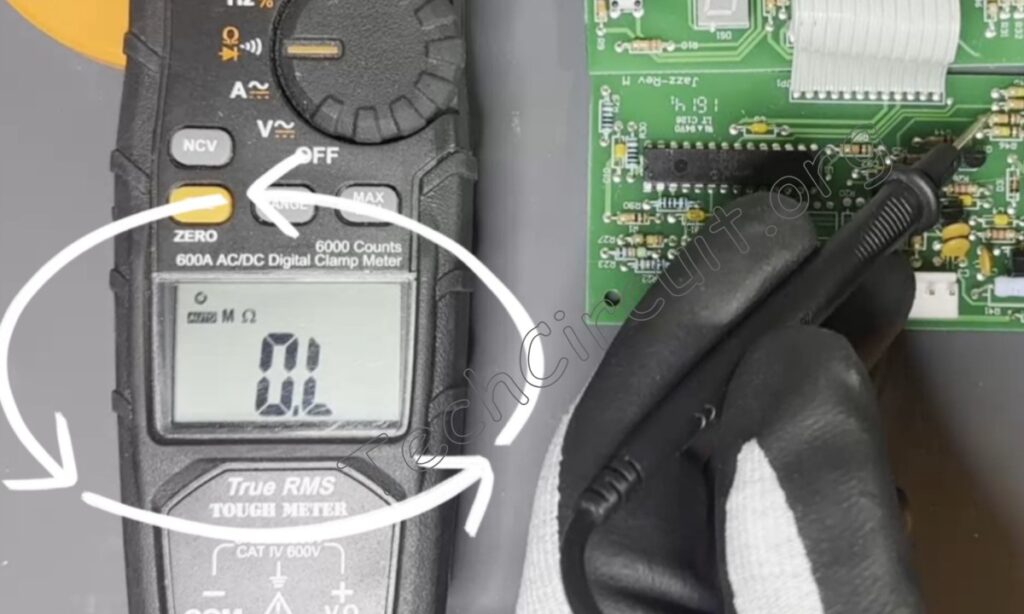
If you see the letters “OL” on the display, that means either the resistor is of too high resistance for the meter, that it is open, or that the probes aren’t firmly pressed onto the resistor leads—the latter two being the most likely. Safety note: Never measure voltage in resistance mode as this can damage the meter or cause injury.
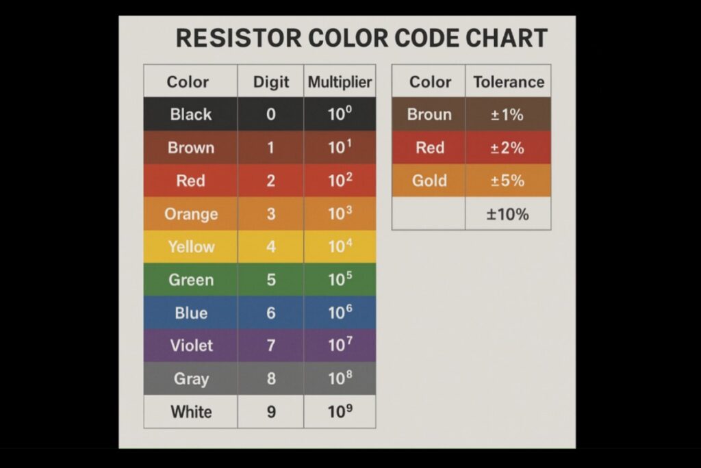
Most resistors have color codes that designate their resistance. There are many resources online for reading resistor color codes.
See the Video Version of this Article
Click HERE, or the image below to view the Video Version of this Article.
Continuity Check
Lots of meters have something called a continuity check. It’s a quick and convenient way of indicating whether a very low resistance is present—less than 50 ohms for this meter. This is handy for testing wires, low-ohm loads like heating elements, and anything that has a resistance of under 50 ohms.

In this mode, the meter will beep when it detects continuity, and if under 50 ohms, will also show its actual resistance.
To access this mode, simply turn the dial here to the resistance mode as before. Note that on the Klein meter, when turning the dial, the text shown in white is a default mode and in orange a mode obtained by pressing the select button. It should default to continuity—if not, press the yellow select button until you see the beep sound symbol.
This meter will now beep anytime a resistance of less than 50 ohms is encountered. Note that for any resistance of greater than 50 ohms, you’ll need to go back to the resistance mode as described earlier by pressing the select button.
Here is continuity mode measuring a wire, as well as a 10-ohm resistor. It beeped to indicate continuity in both cases, as well as show the resistance of each measurement. Note that when I try to measure the 10,000-ohm resistor on the board as previously, there is no beep and nothing on the display. This is to be expected because, again, continuity mode on this meter only detects resistances under 50 ohms. Other meters will facilitate continuity measurements in their own way.
Measuring AC Current
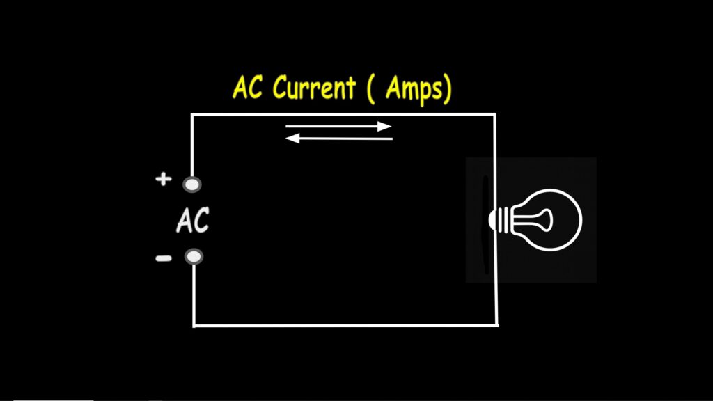
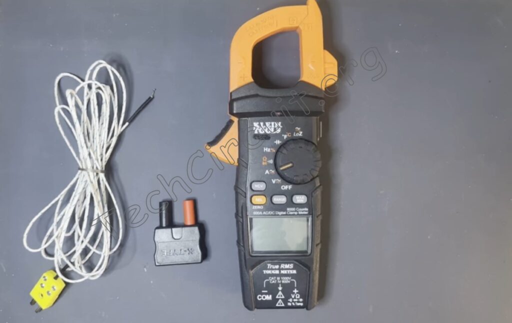
The AC current function measures how much AC current is flowing through a conductor, such as a wire. This is measured in amps. The Klein meter uses a non-contact clamp, allowing you to place the clamp around the conductor you want to test.
To measure AC current, turn the dial to the “A” position as shown here.
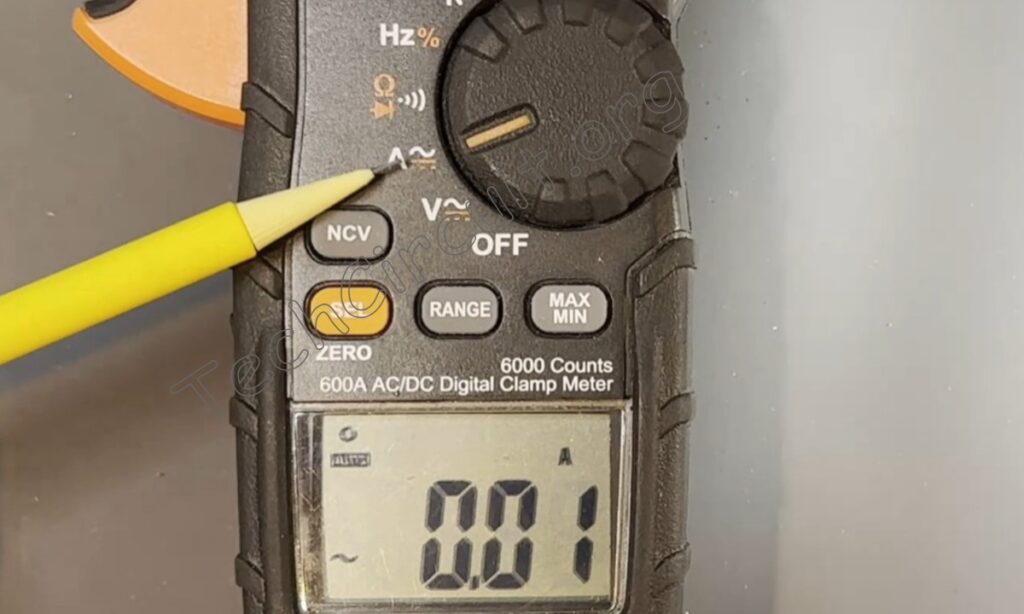
The meter will default to the AC current mode. Then find the single conductor that you want to test and clamp the meter around it.
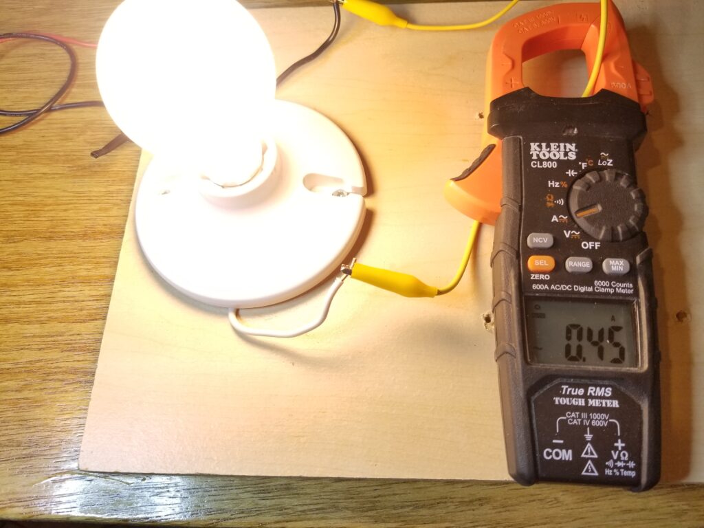
Shown here, the meter is being used to measure the current through a wire connected to a light bulb. The measured current is 0.45 amps. Caution. Dangerous voltages are present in this image. Demonstration only. Don’t try this at home.
Measuring DC Current
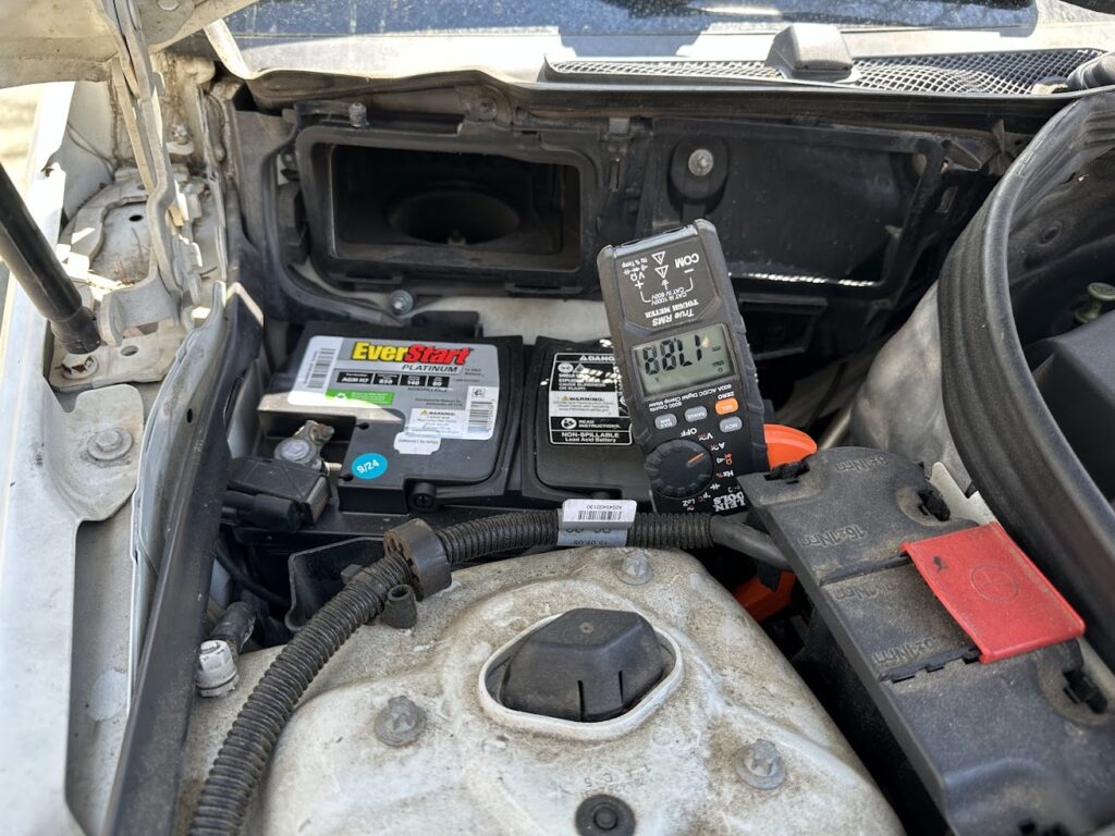
The DC current function is for measuring current that flows in only one direction. It’s also measured in amps. The DC current function is useful for automotive applications, such as checking the starting current of a car battery or determining if a battery is charging or draining.
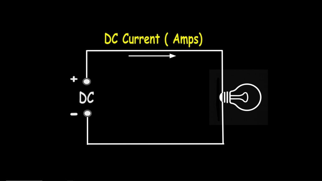
Measuring current with the clamp is done in the same manner as with AC, except polarity must be observed when measuring DC current. Any current flowing from positive to negative will show as a positive reading—if that flow enters the top of the meter.
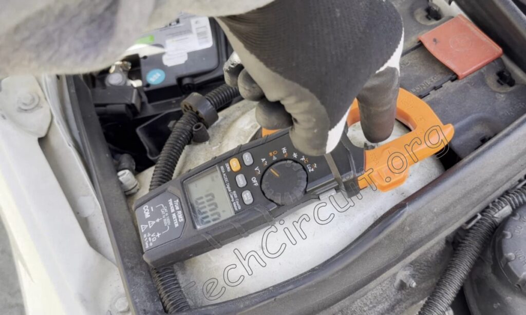
So, if you want to measure the charging current of this battery, you would orient the meter in this way. This picture shows this car battery is charging because current is flowing in the direction of the battery terminal.
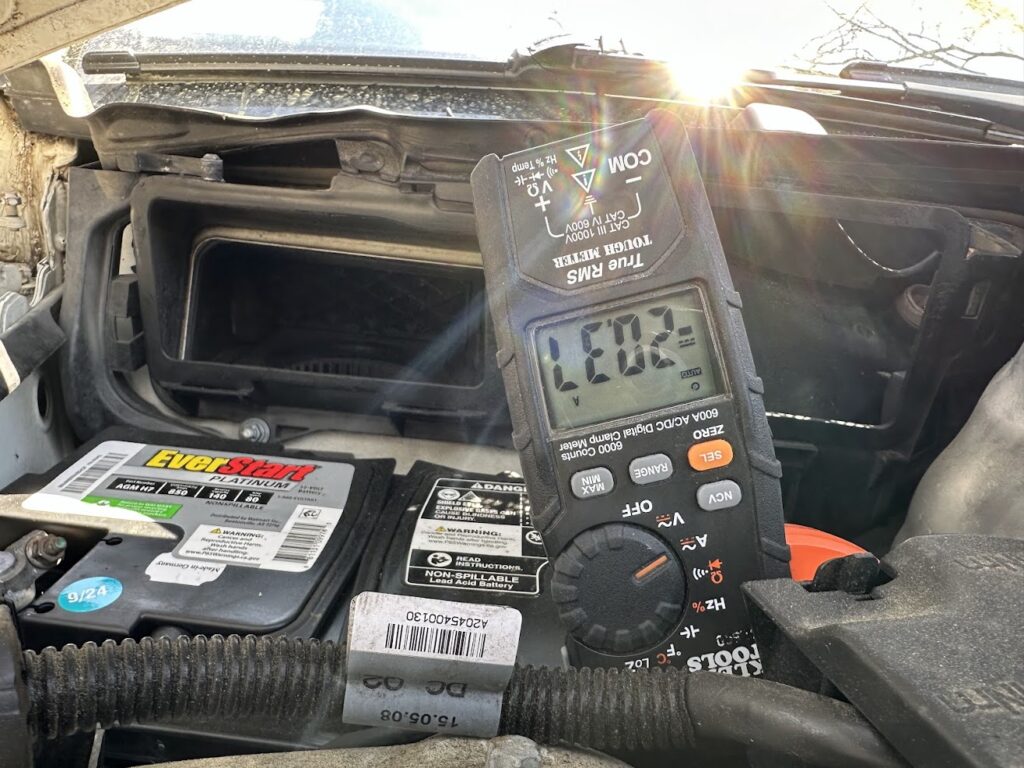
If it was negative, then that would mean the battery is draining—which would be the case if the car was turned off and the headlights were on – as shown below.
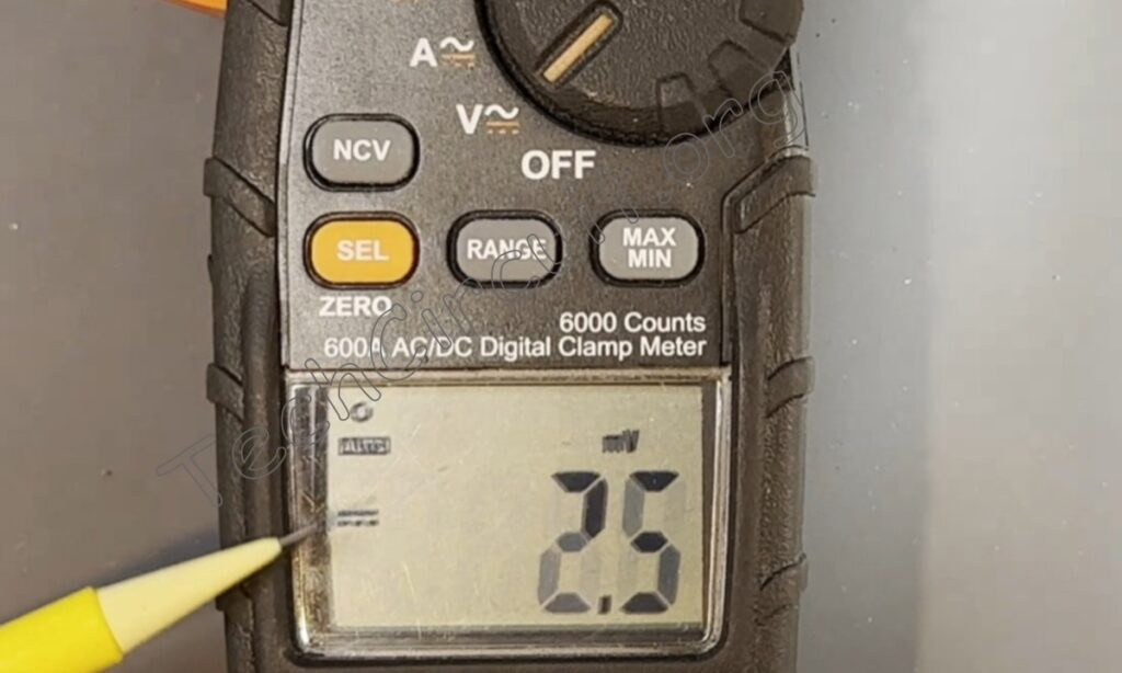
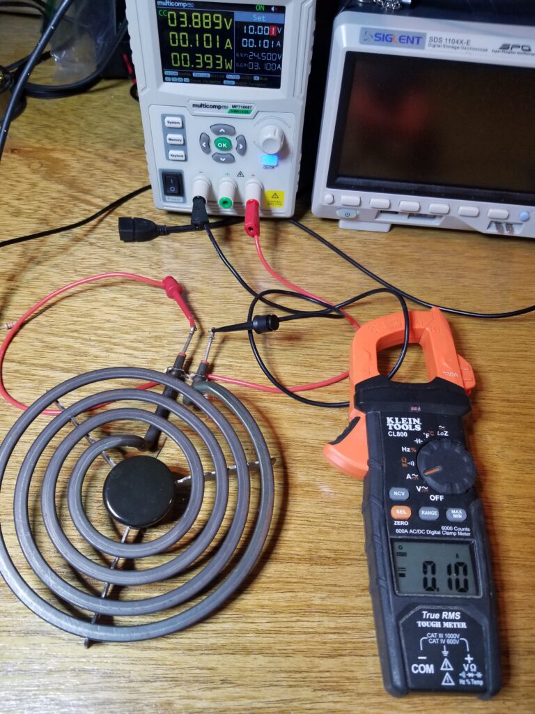
In this image, I show the meter measuring the DC current passing through an electric cooktop element. The amount of current measured is 0.1 amps.
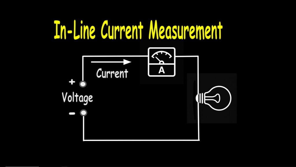
Measuring Current In Line
Some meters don’t have a clamp but still allow you to measure current the traditional way. This way is to place the meter in line with the current flow so that the meter can measure how much current is flowing through it.
Measuring AC Current In Line
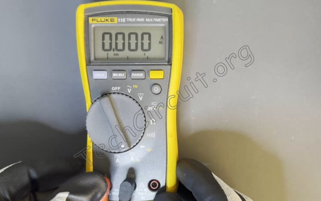
To measure AC current with this method, I turn the dial on this Fluke meter to the AC current mode—as designated by the “A” and the AC symbol. You must take the red lead out of the voltage measurement plug and place it in the amp measurement plug.
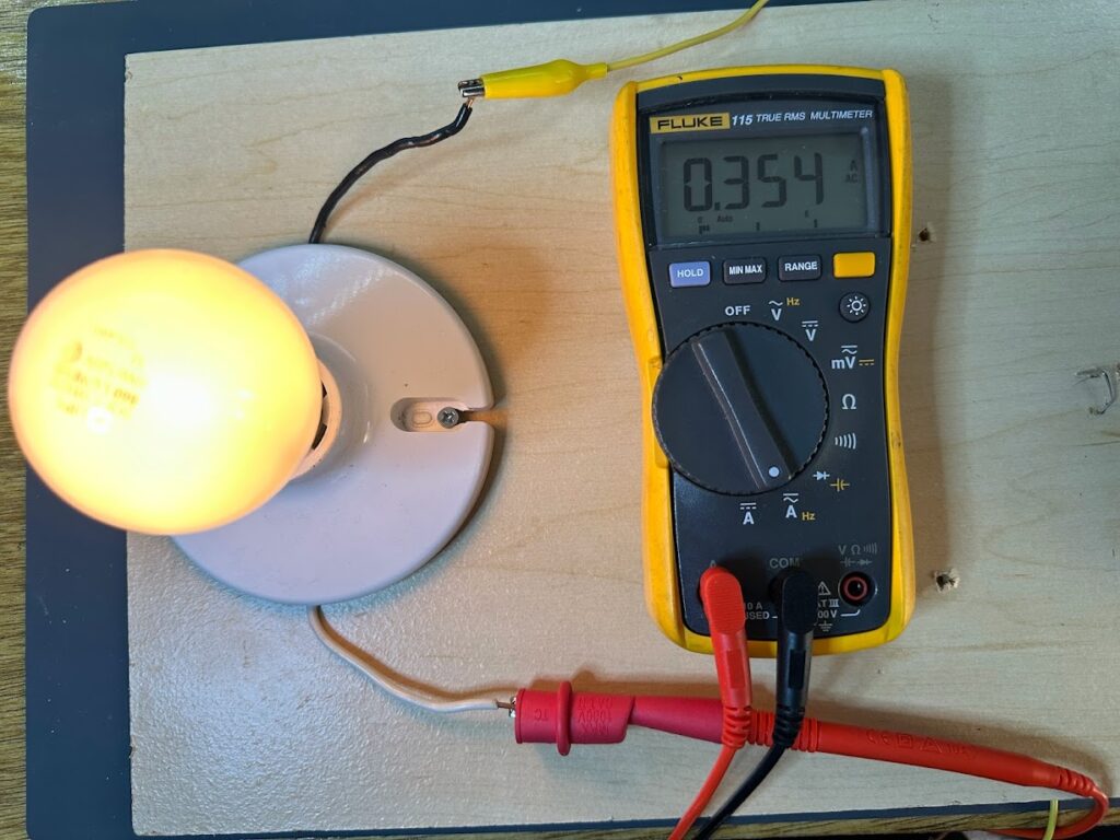
Here’s an example of a Fluke multimeter measuring current in line to determine how many amps it takes to operate this light bulb. Dangerous voltages and potential currents are present in this image. Demonstration only. Don’t try this at home.
Measuring DC Current In Line
You can use the same method to measure DC current as well—just switch over to the DC current mode as shown here. Remember to always disconnect the leads when changing modes on the meter.
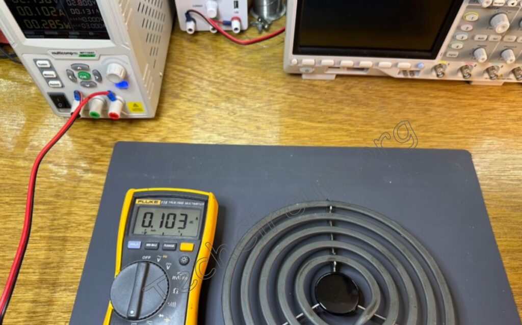
Here’s the same cooktop element used as an example to show that the inline current measurement using this method gives us approximately the same value as when measured with the Klein clamp meter.
A Note of Caution About Inline Measurements
Never use the current function to measure voltage. It is like placing a wire across the battery or an outlet. It will cause a short circuit. Fortunately, most meters have a built-in fuse, but the meter can still be damaged, and it’s a hassle replacing the fuse.
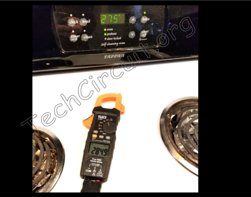
Measuring Temperature
This Klein meter does so by using something called a thermocouple, as shown here.
To measure temperature, turn the dial to the position designated by the white “F” text. This stands for Fahrenheit, which is what the meter defaults to. To measure Celsius, simply press the orange select button.
Here’s an image of the Klein meter measuring the temperature of an electric range oven cycle.
Summary
So those are the very basic functions of multimeters, and they represent the lion’s share of what most people will use them for. To test your newfound knowledge of multimeters, please see the quiz below. For some of the more advanced features, see video #102 on our Youtube channel or CLICK HERE.
I hope you found this article helpful and informative. Thanks for reading!
Test Your Knowledge of Multimeters!
Take the interactive quiz below to shore-up your knowledge of basic multimeter use and theory! Answers at the end of the quiz.
Multimeter Basics Quiz
Select the best answer for each question.
Don’t forget:
“Diverting 10 min/day of social media time towards learning something new, is 5 hours of newfound monthly knowledge.” – SM
To DONATE to the Tech Circuit – CLICK HERE
Alphabetical Links to all Tech Circuit Articles and Blogs – CLICK HERE
Links to all Tech Circuit Cheat Sheets/Field References for Appliance/HVAC Techs – CLICK HERE
For additional electrical and electronics learning material for field techs, visit the following links:
Homepage at http://www.TechCircuit.org
Facebook group at: https://www.facebook.com/groups/746823709133603
Youtube Channel: https://www.youtube.com/@TheTechCircuit
We are a participant in the Amazon Services LLC Associates Program, an affiliate advertising program designed to provide a means for us to earn fees by linking to Amazon.com and affiliated sites.