What are Inlet Valve Diodes?
For some inlet valve solenoids, diodes are used to logically control which valves are energized for a given function. A common configuration is where a safety (or main) valve is energized when either a refrigerator dispenser or icemaker solenoid is energized. In this way, one safety valve can be used for both the dispenser and icemaker circuit. Thus, the safety valve is common to both circuits.
How do the Diodes Work?
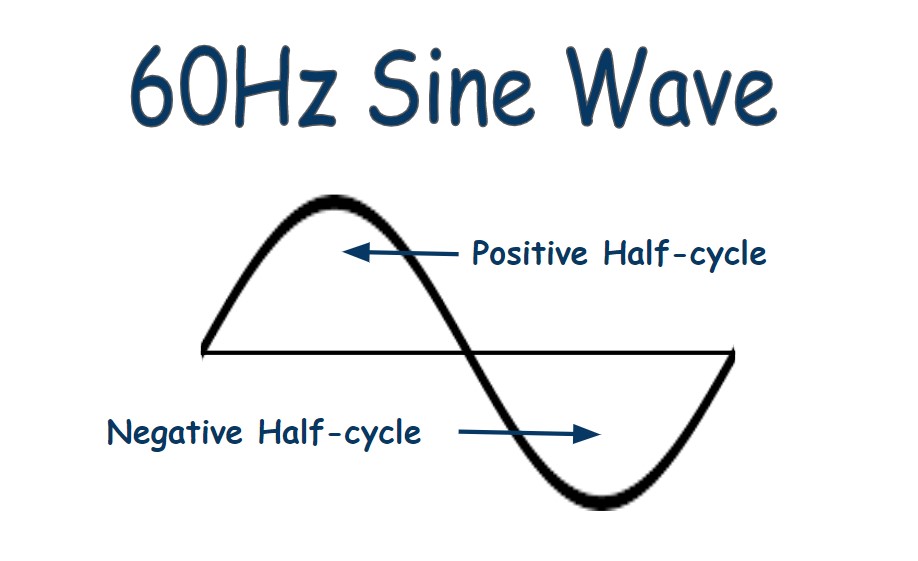
The way a safety valve is energized using diodes based on the fact that a sine wave has both a positive and negative half cycle. Diodes only conduct electricity in one direction. This property is exploited so that the desired sine wave’s half cycle is made available to the safety valve while blocking it from reaching the unused valve.
Diode-based Valve Circuit
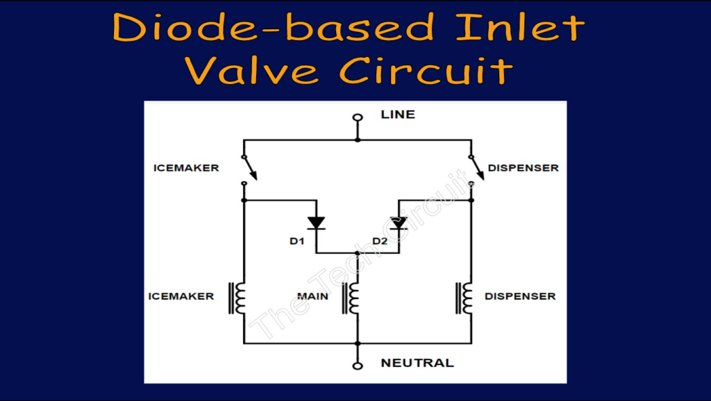
Below is a common circuit that uses diodes for a three-valve configuration. The diodes are oriented so that a positive half cycle of the sine passes through either diode to the main valve, no matter what mode the circuit is in (dispense or icemaker water call).
Dispenser Lever Pressed
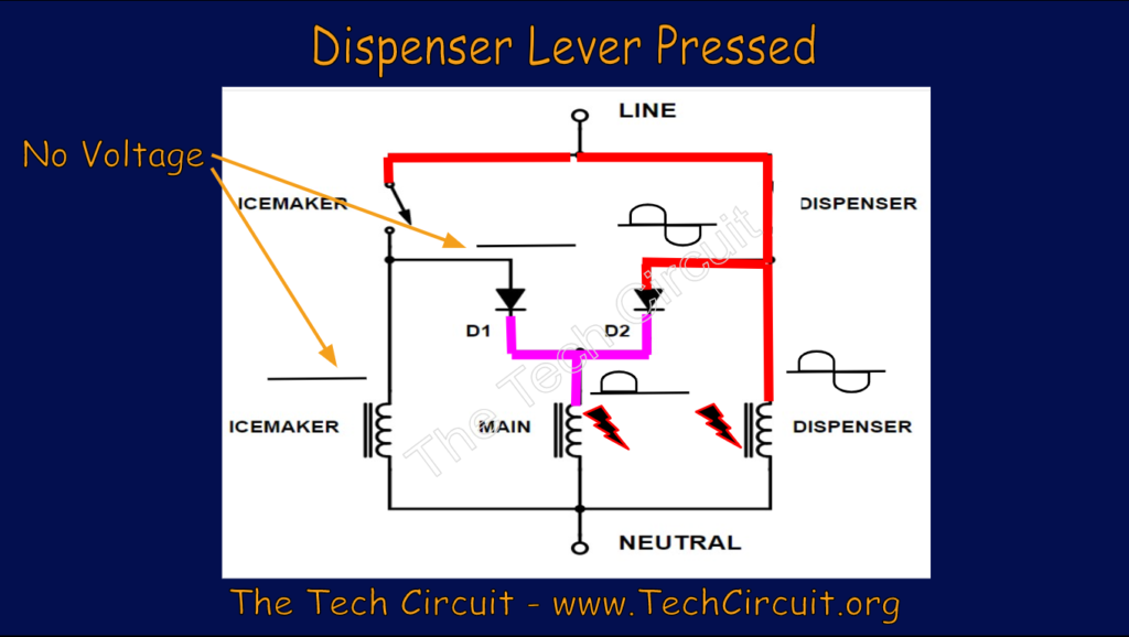
What happens when the user presses the dispenser lever? The dispenser solenoid gets the full sine wave (both half-cycles) as denoted in RED. Only the positive half-cycle makes it through diode D2 as denoted in PINK. Remember that (conventional) current travels through a diode in the direction of the arrow. This is enough though to energize the safety (main) valve solenoid. By the way, the RMS voltage of a half-cycle is 1/2 of the peak value or 85 volts – which, as it turns out, is plenty enough to energize the safety valve. Note that most multimeters (even quality true-RMS meters) won’t read 85 volts because they have a hard time calculating the RMS value of half-wave rectified signals. Note also that the icemaker solenoid gets nothing – as well it shouldn’t. We don’t want the icemaker to fill when we press the dispenser lever. The reason it won’t is because of diode D1. It blocks the positive half-cycle (because it would have to go against the arrow), leaving the icemaker solenoid with 0 volts.
Icemaker Call for Water
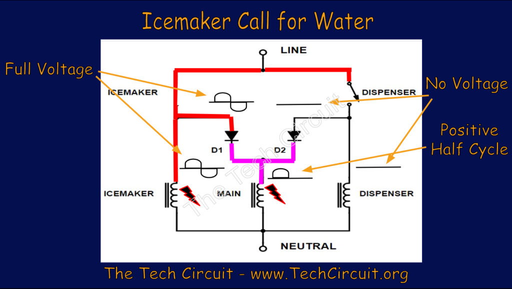
The same thing happens during an icemaker call for water – except that D1 is activated and D2 blocks any voltage from getting to the dispenser solenoid. Remember that RED denotes a full sine wave and PINK is only a half-cycle.
Both Icemaker and Dispenser Valves Energized
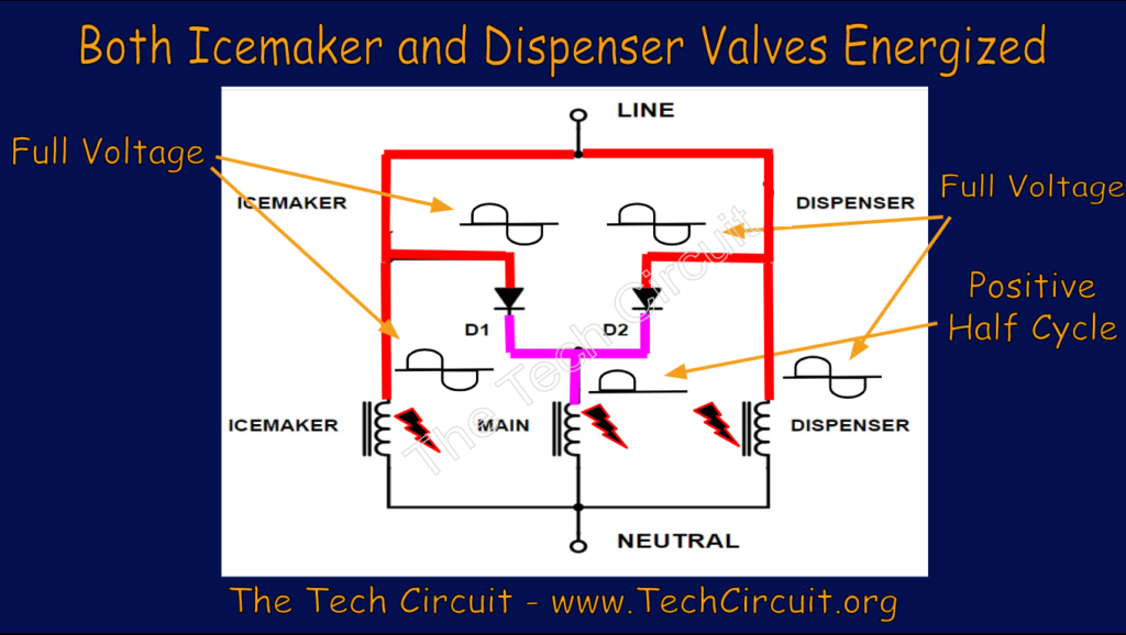
The possibility certainly exists that the icemaker will fill while the user is pressing the dispenser lever. Both the icemaker valve solenoid and dispenser solenoid will then be energized simultaneously. This is because a full sine wave is sent to both the icemaker and dispenser valve as denoted in RED. However, only the positive half-cycle makes it to the safety (main) valve as shown in PINK. This arrangement allows all three valves to be energized simultaneously.
Shorted Diode with Dispenser Lever Pressed
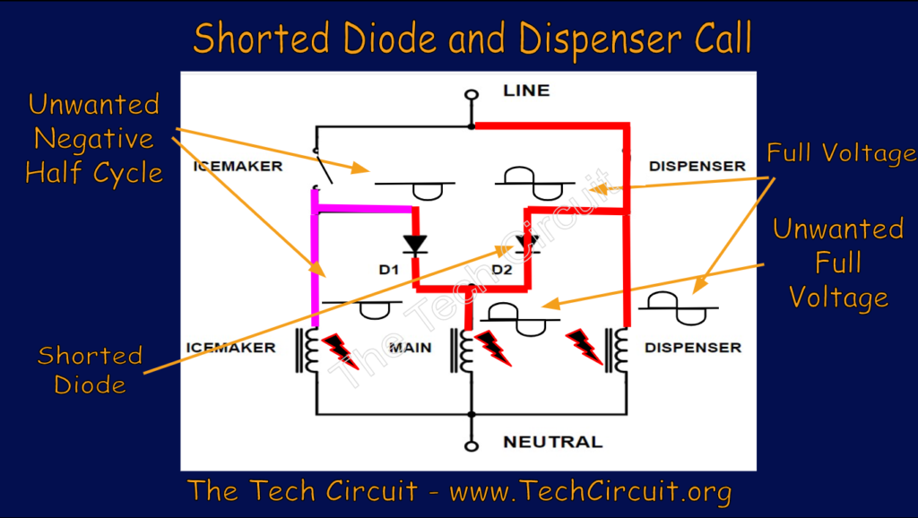
A common failure point in these circuits is a shorted diode. What happens when a user presses the dispenser lever with a shorted dispenser diode (D2) in the circuit? Both the dispenser and safety (main) valve solenoids are energized with a full sine wave as shown in RED. Since a full sine wave appears at the main valve, the negative half-cycle will make its way backwards through diode D1 (since a negative voltage can push current “against” the arrow). This negative half-cycle is 85v RMS and enough to energize the icemaker valve. The net effect is that when the user goes to get dispensed water, the icemaker also fills. In fact, regardless of which diode is shorted – no matter which mode is called (dispense or icemaker water), all solenoids will energize. This fact is a good thing to remember if you ever encounter this stated symptom for a case.
Note that although the safety (main) valve normally reads 85v or less, a shorted diode causes it to get 120v. A common question is whether that will damage the valve. It’s unlikely because the valves are usually rated at 120v.
Test your Knowledge of Inlet Valve Control Diodes!
Understanding Refrigerator Inlet Valve Diodes
Select the best answer for each question.
Summary
Diode-based logical control of inlet valve solenoids is quite common in refrigerators. Technicians will eventually encounter them – and should understand how they work, and what symptoms are likely to accommodate diode failures.
Please see our matching video on this subject:
“Diverting 10 min/day of social media time towards learning something new, is 5 hours of newfound monthly knowledge.” – SM
To DONATE to the Tech Circuit – CLICK HERE
Alphabetical Links to all Tech Circuit Articles and Blogs – CLICK HERE
Links to all Tech Circuit Cheat Sheets/Field References for Appliance/HVAC Techs – CLICK HERE
For additional electrical and electronics learning material for field techs, visit our homepage at http://www.TechCircuit.org or our Facebook group at https://www.facebook.com/groups/746823709133603, or our YouTube Channel
at https://www.youtube.com/c/TheTechCircuit
We are a participant in the Amazon Services LLC Associates Program, an affiliate advertising program designed to provide a means for us to earn fees by linking to Amazon.com and affiliated sites.
