Intro to the Relay Testing Cheat Sheet
This blog shows a diode trick and checklist for fast testing of relays, as well as determining the relay coil voltage. The checklist is further down in this blog.
Important Note
Never attempt to repair circuit boards in appliances or HVAC systems unless you are directly supervised by a professional engineer and doing so under approved ISO and UL processes.
The Flyback Diode Trick
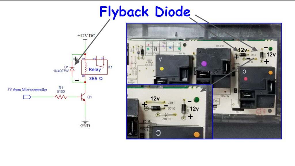
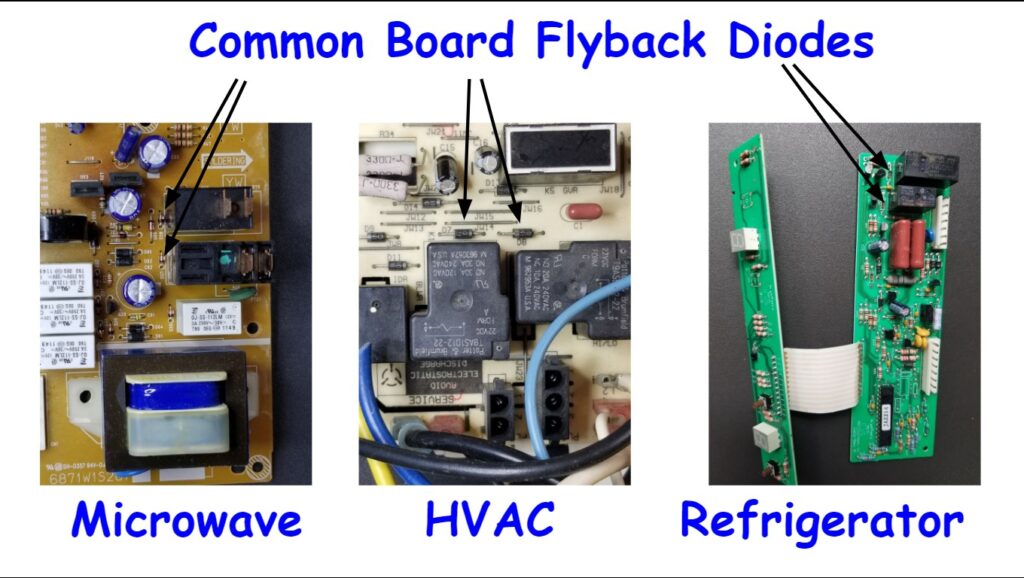
There’s one commonality in relay circuits. That’s the flyback diode in parallel with the relay coil. It protects the driver circuit from the voltage spike caused by collapsing magnetic field when the relay is de-energized. That diode is usually right next to the relay and on top of the board. Since it’s in parallel with the relay coil, it has the DC coil voltage across it when the relay is “on”. If you can’t find it, look for the nearest diode to the relay. Flip the board over to determine if that diode is in parallel with the coil of the relay.
You can easily check to see if the relay “should” be energized by checking the DC voltage across that diode. This method can also be used to tell you what the relay coil voltage should be if it isn’t marked on the relay.
Where the Diode is and How to Check it
Below is a picture of a typical relay circuit and some board pictures – showing where the flyback diode is. Across that diode, you will measure a positive DC voltage corresponding to the coil voltage using your meter on the DC voltage setting. The cathode of the diode is the end with the stripe. That’s where you’ll put your positive lead. The negative side is without the stripe – where the negative lead will go. If you read 12v (for a 12 volt relay), your relay should be energized and the contacts “closed”. Refer to the checklist further below to make your determination of the relay’s functional status, or what the coil voltage is.


Checklist for Testing Relay Functional Status
Identify the flyback diode for your relay of interest. Measure the DC voltage across that diode by putting the positive lead on the banded side and the negative lead on the non-banded side.
The “Subject Load” as mentioned in the checklist, is the load such as the heating element or the motor that should energized.
Below are the specific cases to look for when you check the voltage across the flyback diode:
- CASE 1: DC voltage is present across flyback diode AND you are reading line voltage across relay contacts when the subject load should be energized – SUSPECT FAILED RELAY (BAD CONTACTS, BAD CONTACT SOLDER JOINT, OR OPEN COIL)
- CASE 2: NO DC voltage is present across flyback diode AND you are reading line voltage across the relay contacts when the subject load should be energized – SUSPECT SHORTED FLYBACK DIODE OR OUT OF RANGE THERMISTOR
- CASE 3: If voltage IS present across flyback diode AND the subject load is energized when it shouldn’t be (heat is not selected or motor shouldn’t be running) – SUSPECT SHORTED RELAY DRIVER TRANSISTOR
- CASE 4: If NO voltage is present across flyback diode AND the subject load is energized when it shouldn’t be (heat is not selected or motor shouldn’t be running) – SUSPECT FUSED RELAY CONTACTS
Testing for Relay Coil Voltage
- If you want to replace the relay and are unsure of its voltage, energize the relay using the appliance controls and check the voltage across the flyback diode. It should be within about 1 volt of the relay’s specified coil voltage. Note that some flyback diodes are integrated within the relay driver IC (integrated circuit), or even the driver transistor. In those cases, you’ll need to actually check the relay coil pins to determine the voltage.
Summary
You can use the readily available flyback diode as a test-point for checking relay status. To do so, follow this checklist:
- Identify your relay of interest
- Find the flyback diode for that relay (usually right next to it). It is in parallel with the relay coil.
- Set your voltmeter to DC voltage and connect your leads to the diode as described above.
- Follow the specific checklist in this blog to determine the relay’s status.
- If trying to determine the relay’s coil voltage, the voltage that you read across the diode when the relay should be energized, is your coil voltage.
Disclaimer
This blog is intended for experienced or supervised technicians. Always take appropriate safety precautions when dealing with live circuits. For informational purposes only. Utilize the concepts in this blog at your own risk. The Tech Circuit or Steve Morrison assumes no responsibility or liability for any errors or emissions in the content of this blog. The information contained in this blog is provided on an as is basis with no guarantees of completeness, accuracy, usefulness, or timeliness. Never attempt to repair circuit boards in appliances or HVAC systems unless you are directly supervised by a licensed professional engineer and doing so under approved ISO and UL processes.
Don’t forget:
“Diverting 10 min/day of social media time towards learning something new, is 5 hours of newfound monthly knowledge.” – SM
To DONATE to the Tech Circuit – CLICK HERE
Alphabetical Links to all Tech Circuit Articles and Blogs – CLICK HERE
Links to all Tech Circuit Cheat Sheets/Field References for Appliance/HVAC Techs – CLICK HERE
For additional electrical and electronics learning material for field techs, visit our homepage at http://www.TechCircuit.org or our Facebook group at https://www.facebook.com/groups/746823709133603.
We are a participant in the Amazon Services LLC Associates Program, an affiliate advertising program designed to provide a means for us to earn fees by linking to Amazon.com and affiliated sites.
