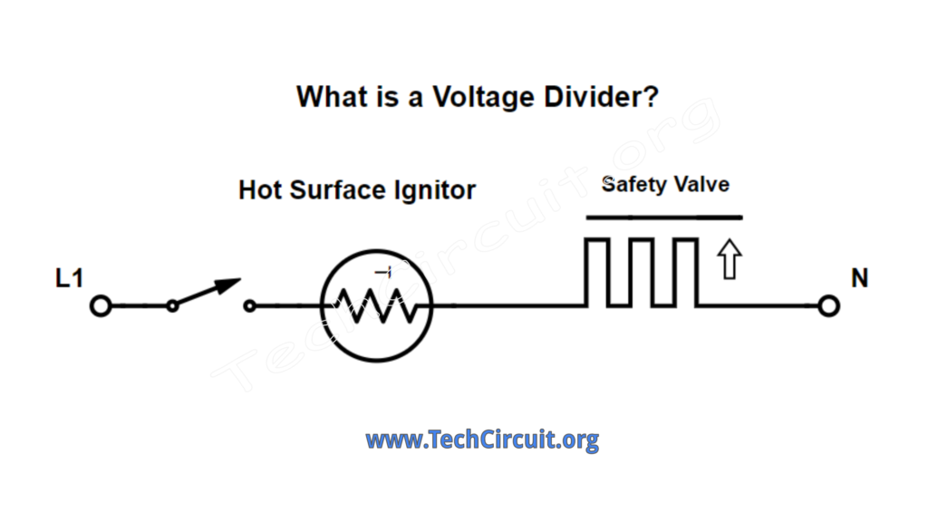
What do floating neutrals, gas dryer valve circuits, Whirlpool electric dryer cool-down circuits, loose terminal block connections, shorted elements, and failing relay contacts all have in common? As the title of this articles suggests – the ever-present voltage divider. They’re everywhere and reside in multiples in every appliance you encounter. They’re not only present in almost every circuit, but are involved in some form in many electrical failures. Knowing how voltage dividers work is a huge step in understanding electricity and electronics. Fortunately, there are just a few simple rules that define them.
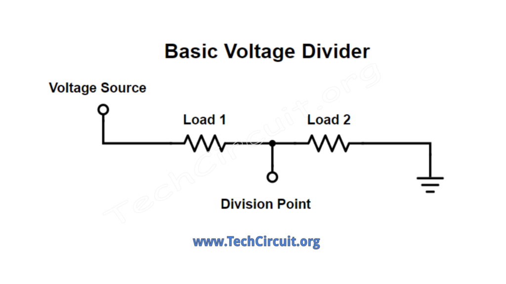
Rule 1: Source Voltage is Divided Among Series Loads
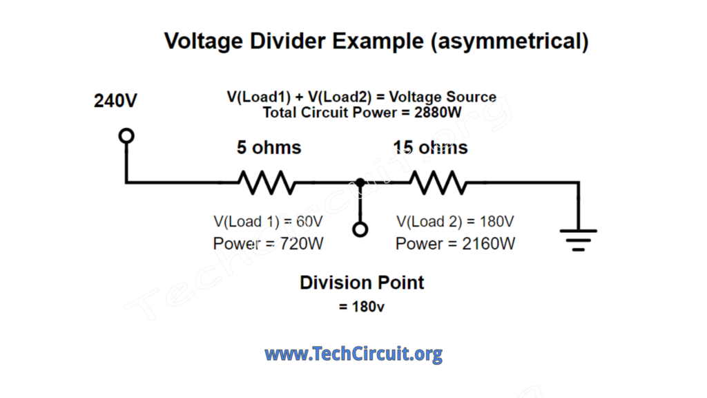
Voltage in a circuit divides itself along a series path. Any resistances in that path will have a voltage drop across them. The higher the resistance, the more voltage. In short, the highest resistance wins. That is simple Ohm’s law. Further, the sum of the voltages in a circuit add up to the supply voltage, which is Kirchhoff’s law. Take a look at this schematic.
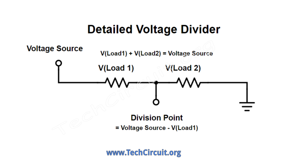
To keep this article simple, we’ll focus mainly on resistive loads like elements. Inductive/resistive loads like motors, gas coils, and valve solenoids, etc. are also part of voltage dividers. However their measured RMS voltages don’t add up to the supply voltage. That’s ok though. As long as we acknowledge that – for our purposes – approximations for those types of loads will do.
Rule 2: Current is the Same Through the Entire Circuit.
As long as there are no parallel branches in the series voltage divider, the current is the same through the entire circuit.
Rule 3: Input Power is Distributed Among the Series Loads
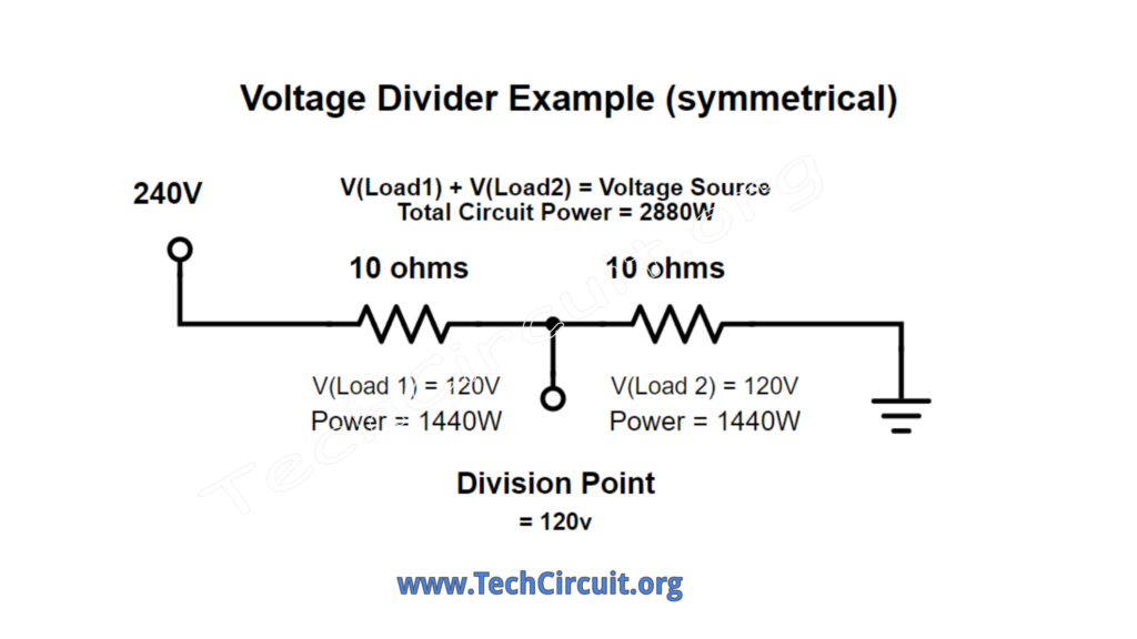
Voltage division also causes multiple loads to exist in a series circuit. In addition to those loads sharing the supply voltage, they also share the amount of total power delivered to that circuit. For example, if you have two 10 ohm elements in series, and a 240v supply voltage, you have 2880 watts of power delivered to the circuit. Each 10 ohm element produces 1440 watts of heat. If the loads were of different resistances, the higher resistance would produce the most heat, but the two loads’ power output would still equal that of the total power input to the circuit. So if one element was 5 ohms and the other one was 15 ohms, the total output power would still be 2880 watts. However the 5 ohm element would produce 720 watts of heat, and the 15 ohm element 2160 watts of heat for a total of 2880 watts. Note again that the higher resistance produces the most heat – which falls in line with the concept that, in a voltage divider, the highest resistance gets the most of the shared supply voltage. The 5 ohm element would get 60 volts, and the 15 ohm element, 180 volts.
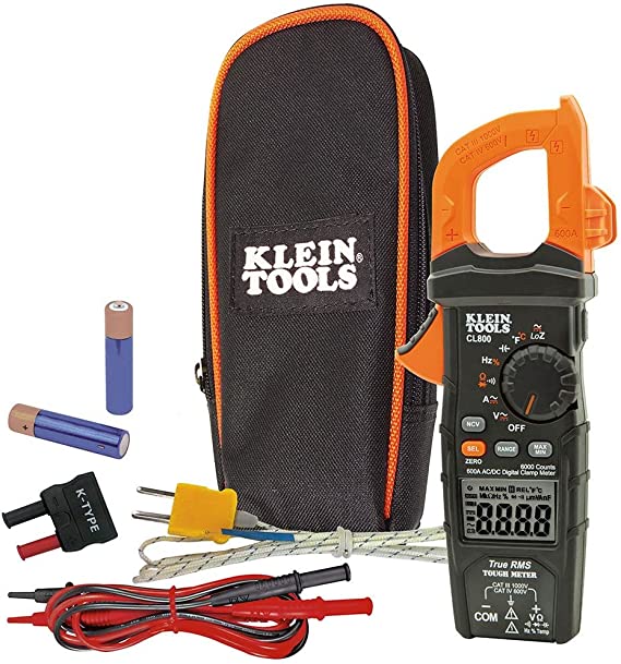
Recommended Multimeter for Field Service
CLICK HERE or Click the image below to purchase our recommended multimeter for field service.
Why is Knowledge of Voltage Dividers Important?
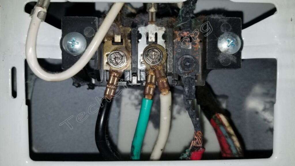
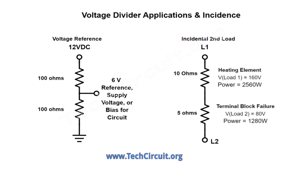
Voltage division in electrical circuits is a natural phenomenon that will occur at every opportunity. Such division can be by design, like with creating voltage references, deriving stepped down supply voltages, biasing of electronic components, and more. Also most commonly, voltage division readily occurs by virtue of failure. A great example of this is when a terminal block fails on an electric dryer, causing a large voltage drop across that terminal block – robbing the intended load of its expected voltage. This concurrently results in a loss of power for the intended load, because the failing terminal block uses up a proportional amount of the total power delivered to the circuit and in effect, becomes a secondary load. This is evident in the apparent extreme heat that the Bakelite block has been subjected to upon visual inspection.
In short, voltage dividers are found throughout the electrical circuitry in appliances, whenever current is drawn from a voltage source, when you use your LoZ meter, and in most any manifestation of high-current circuit failure. Knowledge of how they work, and their associated effects within all of these scenarios is an important piece of the puzzle in your knowledge of electrical theory.
Examples of a Voltage Dividers in Appliances
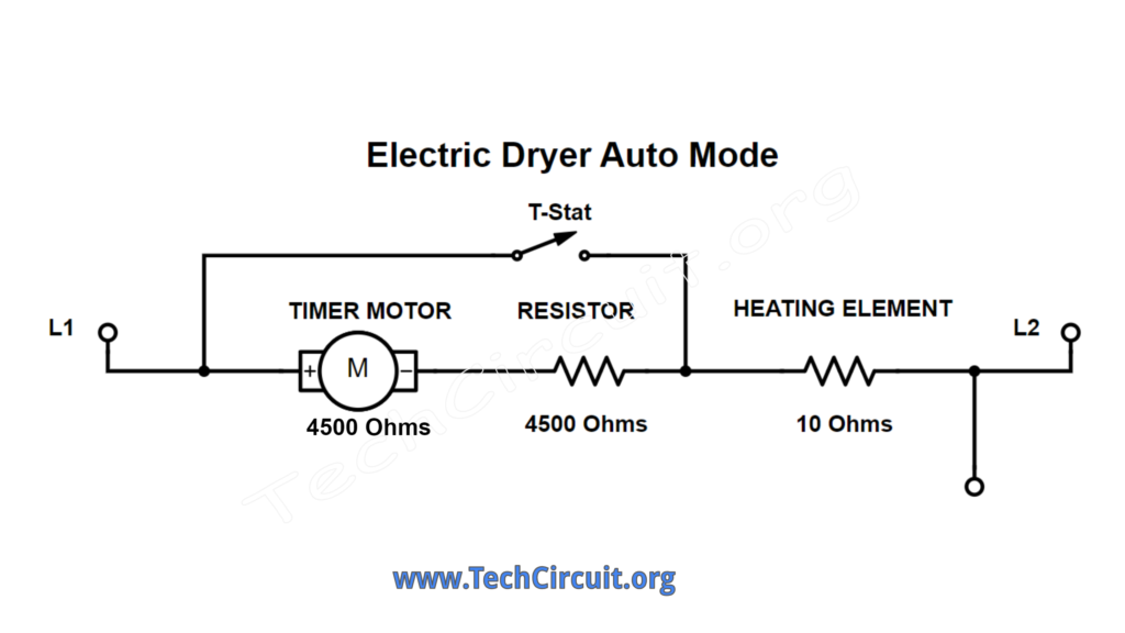
One great example of a voltage divider by design is in a Whirlpool electric dryer that has an “auto-mode”, where the 120v timer motor voltage is derived by splitting the 240v heat circuit voltage in two by a 4.5K resistor and a 4.5K ohm timer winding. The current also flows through a 10 ohm element, which only uses up ( 0.1 %) of the supply voltage – effectively deeming that loss negligible. This voltage division occurs when the thermostat opens and provides a path for the L2 voltage line to seek one side of the timer motor through the voltage divider arrangement.
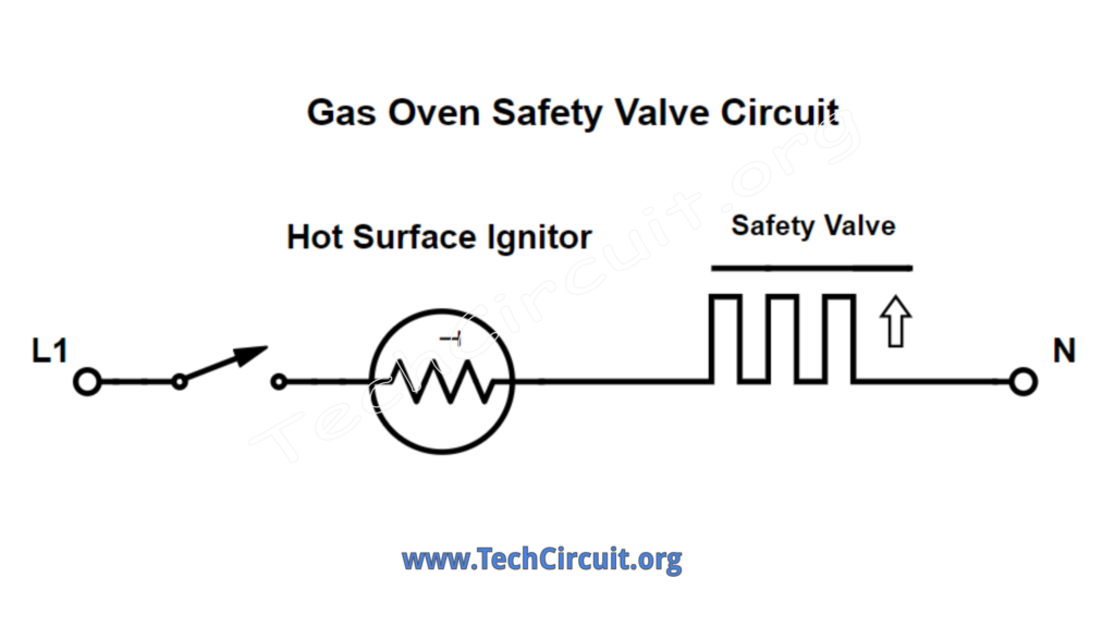
Another example is with electric range glow-ignitor ignition systems. In this arrangement, the safety valve, which has a low impedance, is in series with the glow ignitor, with a relatively high impedance. The ignitor gets most of the voltage (about 116 volts), but some must be available across the safety valve (about 4 volts) in order to supply it enough power to heat up a bimetal strip and open the valve. Such a design depends on the voltage division concept for both the ignitor and the valve to perform their functions.
How to find the Voltages in the Divider
One can find the voltage of each load very easily by just using ohms law. Given the example in the image below, the total resistance of a series circuit is the sum of all resistances (20 ohms). The circuit current which is the same throughout the entire circuit is the supply voltage divided by that total resistance (12 amps). To find the voltage drop across each load you can simply multiply the resistance by the current per Ohm’s law (10 ohms x 12 amps – 120v). If you do that with each load and sum up the voltages across each load, your total voltage will be equal to the supply voltage (120v + 120v = 240v).

Alternately, you can use the voltage divider equation which for a given load takes the percentage of that load’s resistance divided by the total, and is multiplied by the source voltage. This will give you the voltage across your load of interest. Below is that equation.
V(load) = V(source) x ( R(load) / ( R(total)))
Thus for a 240v source voltage and two 10 ohm loads, to find the voltage across one of the loads you have:
V(load1) = 240v x (10 ohms / 20 ohms) = 240v x 0.5 = 120v.
This yields the same answer as using simple Ohm’s law.
Video on Voltage Dividers
For my video on voltage dividers for field technicians, CLICK HERE or click on the video below:
Test your Practical Knowledge of Voltage Dividers!
Understanding Voltage Dividers
Select the best answer for each question.
Don’t forget:
“Diverting 10 min/day of social media time towards learning something new, is 5 hours of newfound monthly knowledge.” – SM
To DONATE to the Tech Circuit – CLICK HERE
Alphabetical Links to all Tech Circuit Articles and Blogs – CLICK HERE
Links to all Tech Circuit Cheat Sheets/Field References for Appliance/HVAC Techs – CLICK HERE
For additional electrical and electronics learning material for field techs, visit the following links:
Homepage at http://www.TechCircuit.org
Facebook group at:
https://www.facebook.com/groups/746823709133603
Youtube Channel: https://www.youtube.com/@TheTechCircuit
We are a participant in the Amazon Services LLC Associates Program, an affiliate advertising program designed to provide a means for us to earn fees by linking to Amazon.com and affiliated sites.
