Intro – Resistor Voltages and Currents – The Basics
Reading schematics can sometimes be confusing for Appliance and HVAC technicians. Particularly determining voltages across or current through components. These voltages and currents are well defined by Ohm’s Law though. No matter how a network of components are arranged in a circuit, there is a formula to determine what voltages appear at certain points and how much current flows through each component. If you are a technician and can make it through and understand all of the following examples, you will have an excellent foundation for reading and troubleshooting resistive circuits in schematics. If you don’t understand a concept, re-read it until you do, before going on to the next example. It will be well worth it. Consider the simple circuit below:
Two quick rules about Voltage and Current:
1) Voltage appears at points in a circuit.
2) Current flows through components or parts of a circuit.
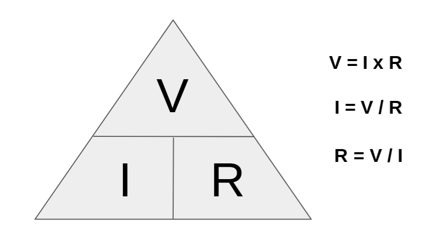
Ohm’s Law is important for answering all of the following questions for the following diagrams.
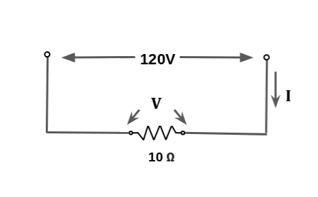
Keeping this in mind, let’s answer the following questions for
Case 1:
A) Referring to the Case 1 circuit above, what is the voltage across the 10 ohm resistor?
ANSWER: It is simply the supply voltage of 120V. Why? Because there are no components between the power supply and the resistor and thus nothing to drop the voltage.
B) What is the current through the 10 ohm resistor?
ANSWER: Use Ohm’s Law. I=V/R. Thus I = 120/10 = 12 Amps.
Case 2:
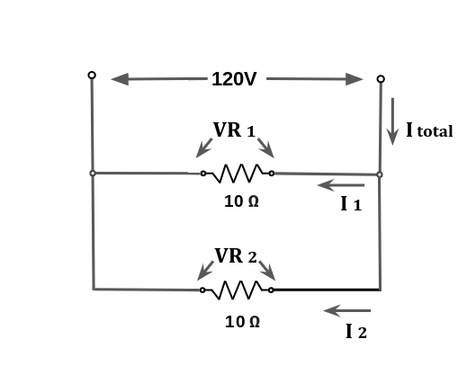
Case 2: Consider the following circuit diagram. We now have 2 resistors in parallel. Let’s answer the following questions:
A) For the Case 2 diagram below, what are the voltages VR1 and VR2?
Answer: It is quite simple. For the same reason as in Case 1, there are no components to drop the voltage before it appears at the resistors – there is only a wire of zero ohms connecting them. Thus, both R1 and R2 have the same voltage which is 120 Volts . It is important to note here that the voltage does not get to R1 before it gets to R2. Since voltage “appears”, it is at both resistors at the “same” time.
Thus the ANSWER is 120 Volts at both resistors.
B) For Case 2, what is the current (I total) ?
Answer: To calculate this, we need to know the total resistance of R1 and R2 combined. Since they are in parallel, we use the parallel resistance equation:
1 / Rp = 1 / R1 + 1 / R2
Plugging in the numbers we have 1 / Rp = 1/10 + 1/10 = 1 / 0.2 = 5 ohms
Now that we know parallel resistance of R1 and R2. This means that the voltage source actually sees 5 ohms. This I total, using Ohm’s Law is I = V / R or
I = 120 / 5 or 24 Amps.
Thus the ANSWER is 24 Amps.
C) For Case 2 above, what are the currents through the resistors R1 (I1) and R2 (I2)?
You will simply use Ohm’s Law. We know VR1 and R1’s resistance. Thus
I1 = VR1 / R1 = 120 / 10 = 12 Amps. Both resistors have the same resistance, so it is the same for both.
Thus the ANSWER is 12 Amps for each.
Alternately, but not necessary in this case, you can use the current divider formula which is
I1 = I total (R total/ (R branch ) = 24 Amps (5 ohms/10 ohms) ) = 24 (5/10) = 24 x 0.5 = 12 Amps for each branch.
Click the Image Below to Purchase the Klein CL800 Clamp Meter

Now on to voltage dividers. One of the more common configurations you will encounter.
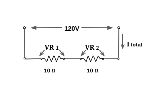
Consider the Case 3 circuit below. It is a simple voltage divider network. The 120V supply will be divided between the two resistors. How it divides depends on the resistance of R1 and R2. In our example, they are both the same, so it is easy to visualize. Let’s answer the following questions for Case 3:
Case 3:
A) For the Case 3 diagram below, what is the total resistance of the circuit?
ANSWER: Since R1 and R2 are in series, the total resistance is R1 + R2 = 10 + 10 = 20 ohms.
B) For Case 3, what is I total?
Well we know the total resistance so all we need to do is plug it into the Ohm’s Law equation: I = 120 / 20 = 6 Amps, which is the same all the way through the circuit, since there is only one path.
Thus the ANSWER is 6 amps.
C) For Case 3, what is VR1?
There are 2 ways to calculate it. First, we know the current right? The current is the same all the way through the circuit. The current through R1 and R2 is the same as I total since there is only a single current path through the circuit. Thus VR1 is V = I x R or VR1 = 6 amps x 10 ohms = 60 volts. The calculation for VR2 is the same since R2 it has the same resistance as R1.
Alternatively you can use the voltage divider network formula which is
VR1 = V total ( R1 / (R 1 + R 2) ) = 120V ( 10 / 10 + 10 ) = 120V ( 0.5) = 60 volts.
Thus the ANSWER is VR1 = 60 volts.
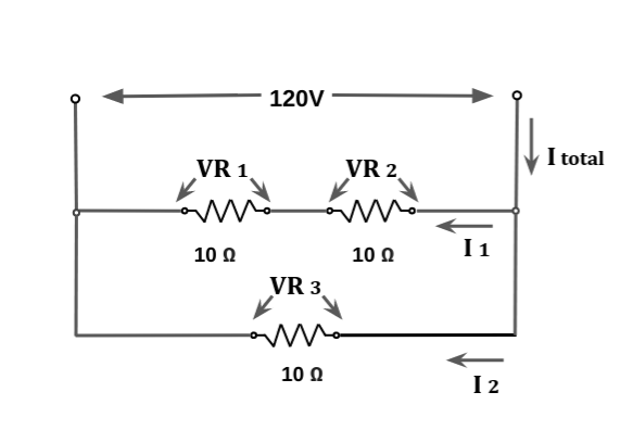
Case 4:
Consider the following diagram. You have R1 and R2 in series, and R3 in parallel with R1 and R2. It may look complicated, but you only need to first combine R1 and R2 to find the series resistance, and then combine that with R3 to find the total parallel resistance of the circuit – in order to find I total. Once you find that, you’re set. The best way to do it is step by step as follows:
A) For Case 4, what is the total resistance of the circuit as seen by the 120 volt supply?
First let’s find the total resistance of R1 and R2 combined. This is simply R1 + R2 or 20 ohms.
Now we find the parallel resistance of that and R3. We simply use the parallel formula again. It is 1 / Rp = 1 / Rs + 1 / R3, where Rs = the series resistance of R1 and R2. Thus 1 / Rp = 1/20 + 1/10 = .05 + 0.10 = 0.15.
1 / Rp = 0.15 thus Rp = 1 / 0.15 = 6.7 ohms.
Thus the ANSWER is 6.7 ohms.
B) For Case 4, calculate I total.
Very simply, it is, using Ohm’s Law, it is I = V / R = 120 v / 6.7 ohms = 18 amps rounded.
Thus the ANSWER is 18 amps.
C) For Case 4, calculate I 1 and I 2.
This is easier than it looks. We know the voltage across each path right? Thus I1 = V / R = 120v / R1 + R2 = 120v / 20 ohms = 6 amps.
I2 = V / R = 120 / 10 = 12 amps.
Note that I 1 + I 2 = I total as found above. This is not a coincidence. It is necessary. I1 + I 2 must equal I total.
Thus the ANSWER is I1 = 6 amps and I2 = 12 amps.
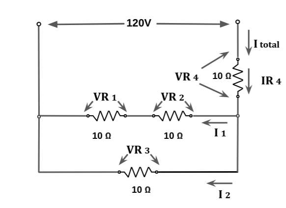
Case 5:
The final case is a little more complicated, but if taken step by step it is not difficult. We will draw on our answer from Case 4A to get our total resistance of the 2 branches. Consider the Case 5 circuit below:
A) For Case 5, what is the total parallel resistance of the two lower branches?
NO need to recaculate this as it is answered by Case 4A and is 6.7 ohms.
Thus the ANSWER is 6.7 ohms.
B) For Case 5, what is the total resistance of the circuit as seen by the 120V supply?
Since part of the question is answered above in 5A, we only now have a series resistance circuit. It is 6.7 ohms + R4 or 6.7 + 10 = 16.7 ohms. It is easy when done step by step! Now that we know that, we can easily find I total.
Thus the ANSWER is 16.7 ohms.
C) For Case 5, what is I total?
It is simply I = V / R or I = 120 / 16.7 ohms = 7.2 amps.
Thus the ANSWER is 7.2 amps.
Now that we know that, we can find VR4 and VR3
D) For Case 5, what is VR4?
Easy, V = I x R or V = 7.2 x 10 = 72 volts.
The ANSWER is VR4 = 72 volts.
Because of the voltage divider rule, the remainder of the voltage will appear across R3 and also across the series branch of R1 and R2.
E) For Case 5, what is VR3?
There are several ways to calculate this, but it is simply the remainder of the voltage left over after R4 drops 72 volts.
Thus VR3 = 120 – 72 = 48 volts.
Thus the ANSWER is 48 volts.
This also appears across the series R1 and R2 branch. With this, it is easy to calculate I1 and I 2.
F) For Case 5, what is I 1 and I 2?
Easy. We know the voltage across each branch.
I 1 = V / R or 48 / 20 or 2.4 amps.
I 2 = V / R or 48 / 10 or 4.8 amps.
Note that I1 and I2 once again equal I total (answer 5c) which is not only necessary, but is a good way to cross check the answers.
Thus the ANSWER is I1 = 2.4 amps and I2 = 4.8 amps.
If you have read and understood all of the above problems and concepts, you should be able to more easily interpret such circuits on schematics and circuit boards.
Don’t forget:
“Diverting 10 min/day of social media time towards learning something new, is 5 hours of newfound monthly knowledge.” – SM
To DONATE to the Tech Circuit – CLICK HERE
Alphabetical Links to all Tech Circuit Articles and Blogs – CLICK HERE
Links to all Tech Circuit Cheat Sheets/Field References for Appliance/HVAC Techs – CLICK HERE
For additional electrical and electronics learning material for field techs, visit our homepage at http://www.TechCircuit.org or our Facebook group at https://www.facebook.com/groups/746823709133603.
We are a participant in the Amazon Services LLC Associates Program, an affiliate advertising program designed to provide a means for us to earn fees by linking to Amazon.com and affiliated sites.