What Does Line Voltage Look Like?
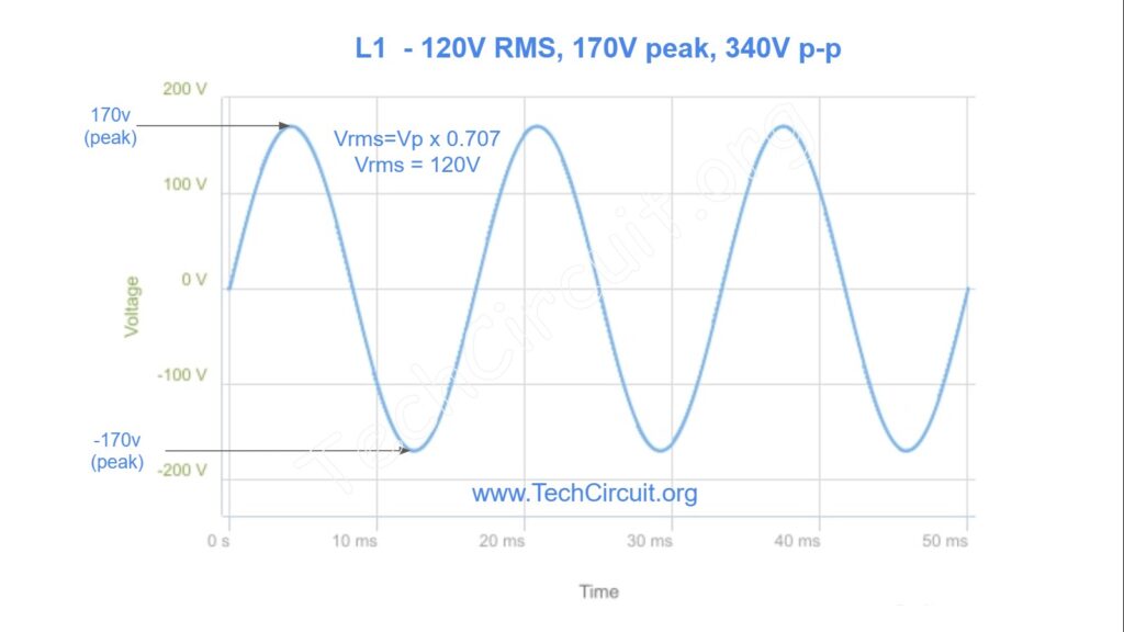
Appliance and HVAC technicians frequently deal with residential line voltage. Failures in appliances and HVAC systems are sometimes caused by mis-wired, loose, or disconnected components. Understanding the behavior of voltages when they are missing or mis-wired can aid in troubleshooting. A 60Hz, 120V RMS voltage is determined by multiplying the sine wave peak value by 0.707. The peak value of 120V RMS is 170V, which can conversely be determined by multiplying the RMS value of 120V by 1.41. Why is this relevant?
Be sure to subscribe to our Youtube Channel!
For tons of videos on electrical and electronics diagnostics, practical electrical theory, and field-technician resources, click the picture below or this link here: https://www.youtube.com/@TheTechCircuit?sub_confirmation=1

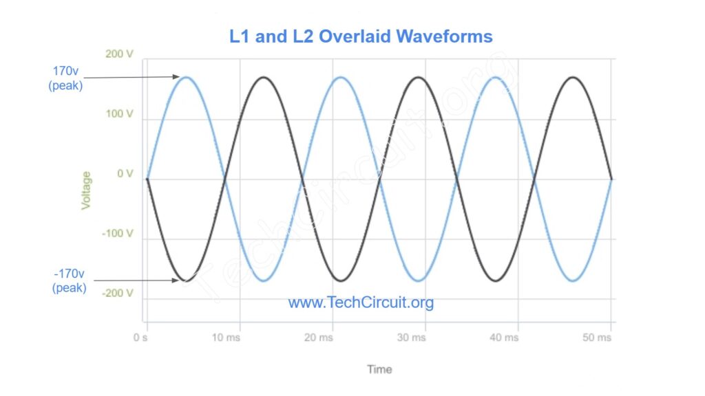
For one, the 170v peak value (with respect to neutral or ground) is what the technician is actually exposed if they were to touch L1. This is opposed to 120v DC, where 120v is the maximum value that would be present. It is widely accepted that AC voltage is more dangerous than DC for a given voltage. Also, the oscillating nature of AC, along with the 60Hz frequency makes it particularly dangerous because how it affects conductivity through the skin. The 170v peak value is also important because if rectified and filtered by capacitors, it would be the actual voltage stored on those capacitors. For some types of power supplies, this is a critically important fact. Although the peak value is 170v, the peak-to-peak value is double that, or 340v – but does not happen simultaneously. This is shown in the waveform below where the 0V on the Y axis represents neutral.
What Does RMS AC Voltage Mean?
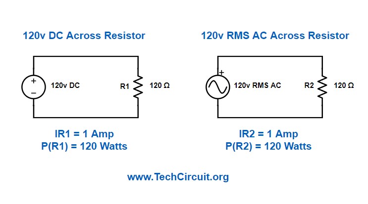
Although the positive and negative half cycles don’t happen simultaneously, the energy of each half cycle is typically “stored” in the form of heat, mechanical momentum (like in a motor), with a voltage doubler (like in some power supplies), or other means. So the RMS (root mean square) voltage is the DC equivalent in terms of how much power would be delivered to a resistive load. In other words, either 120v DC or 120v RMS AC connected to a 120 ohm resistor will both deliver 120 watts of power to that resistor. By the way, that is P=V²/R.
How is Line Voltage Derived?
In most North American households, 120v RMS is only one leg of a single phase 240v system. That system is actually “split-phase”. The 240v is derived from a step-down transformer attached to the incoming power lines. It uses a center-tap to define neutral. This neutral is bonded to ground at the breaker panel and is the reference for either the L1 or L2 120v legs. So when you plug in a lamp, it is receiving 120v RMS line with respect to neutral.
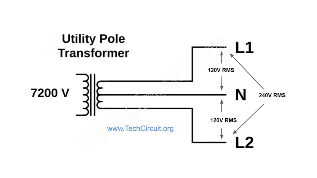
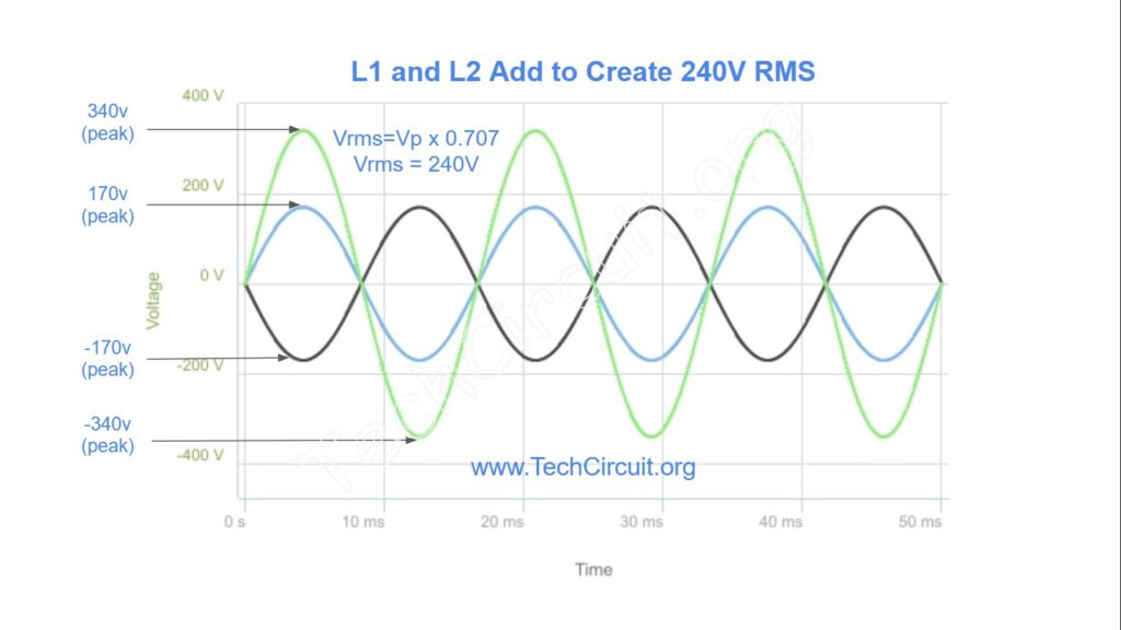
When L1 and L2 are combined they form a 240v RMS voltage. This is because the “peak” difference between L1 and L2 is 340v – and RMS = (peak) x 0.707 or 240v. Since L1 and L2 are opposite each other they are 180 degrees out of phase when referenced from neutral only. This is why it is referred to as a single “split-phase” system. However, when referenced from either L1 or L2, the 120v segments are in-phase with each other and additive – for a total of 240v. So for all intents and purposes, both L1 and L2 in a split phase system are in-phase with each other. An oscilloscope image of L1 with respect to L2 is shown below. As you can see, at the highest peaks, the voltages are 340 volts away from each other with respect to neutral – which is the peak value used to calculate the 240v RMS value. When both lines intersect, the peak voltage of the combined waveform is 0 volts. This represents the zero crossing point of the 240v RMS voltage.
Below is shown an oscilloscope image of the resulting waveform based on the combined L1 and L2 voltages. You can see when both L1 and L2 are at their respective peak values (positive and negative), that the resultant larger waveform is 340v peak and and 680v peak to peak.
Recommended Oscilloscope
Why Referencing Neutral in 240v Diagnostics can be a Bad Idea
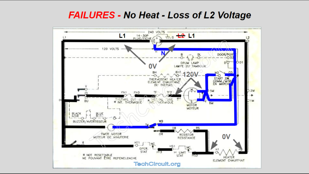
Technicians can sometimes become confused when dealing with appliances that have lost L2, for example. If L1 passes through a dryer element and appears at the L2 terminal, they may mistakenly assume that both L1 and L2 are functioning properly, as they measure 120V with respect to neutral on both sides. However, this is not the case. In reality, both sides are actually reading the same 120V because L1 and L2 are 180 degrees out of phase with each other when referenced from neutral. This fact becomes relevant in certain diagnostic scenarios. The failure case below illustrates this for an electric dryer, where the leg on the right side of the terminal block should be L2. When the dryer is on and in heat mode, L1 passes through thermal devices, the heating element, and the motor’s centrifugal switch, and appears where L2 should be. Using ground as a reference is even more problematic because, although it should be connected to neutral in the breaker box, its potential may differ from neutral or it may not even be connected to the appliance chassis. <FULL ARTICLE ON DIAGNOSTIC REFERENCING CAN BE FOUND HERE>
To summarize, common residential line voltage has the following properties:
- Neutral is bonded to Earth ground at the main panel.
- In a split-phase system, referenced from either L1 or L2, the 120v segments are in-phase with each other and are additive, for a total voltage of 240v RMS.
- L1 and L2 are 180 degrees out of phase from each other only when referenced from neutral (which is the center-tap of the residential step-down transformer).
- The voltages from L1 to L2 are: 240v RMS, 340v peak, and 680v peak to peak.
- The voltages from L1 or L2 to neutral are: 120v RMS, 170v peak, and 340v peak to peak.
- RMS AC voltage is the DC voltage equivalent in terms of its ability to deliver power to a resistive load (like a heating element).
- The actual maximum voltage that technicians are potentially exposed to at any instant in time is 170v for 120v RMS and 340v for 240v RMS.
- It is not advisable to reference neutral (or ground) when troubleshooting 240v appliance circuits because neutral is typically not part of that circuit, and most multimeters can’t tell the difference between L1 and L2 from that reference. The technician may think they are measuring L2 when they are actually measuring L1 (that is being fed back through a load in the circuit).
- Referencing from neutral only makes sense when you are assessing the integrity of the voltage source and no external load is connected to that source.
Please see our matching video on the subject below:
Test Your Knowledge!
Test your comprehension of this material, and see how high you can score. The quiz answers are at the end:
- What is the peak voltage of a 120V RMS sine wave?
- A) 120V
- B) 170V
- C) 240V
- D) 340V
- Why is AC voltage considered more dangerous than DC voltage at the same level?
- A) AC voltage has a higher peak value.
- B) AC voltage oscillates, affecting skin conductivity.
- C) AC voltage has a higher RMS value.
- D) AC voltage is more stable.
- In a split-phase system, what is the RMS voltage when combining L1 and L2?
- A) 120V
- B) 170V
- C) 240V
- D) 340V
- What is the purpose of the center tap in a step-down transformer for residential line voltage?
- A) To provide 240V
- B) To define neutral
- C) To increase voltage
- D) To decrease current
- How are L1 and L2 oriented in a split-phase system when referenced from neutral?
- A) In-phase
- B) 90 degrees out of phase
- C) 180 degrees out of phase
- D) 270 degrees out of phase
- What is the peak-to-peak voltage of a 120V RMS sine wave?
- A) 120V
- B) 170V
- C) 240V
- D) 340V
- Why is the RMS voltage significant in AC systems?
- A) It represents the peak voltage.
- B) It indicates the average voltage.
- C) It equates to the DC equivalent power delivered to a resistive load.
- D) It shows the peak-to-peak voltage.
- What is the peak voltage difference between L1 and L2 in a split-phase system?
- A) 120V
- B) 170V
- C) 240V
- D) 340V
- When L1 and L2 are combined in a split-phase system, how do their 120V segments behave?
- A) They cancel each other out.
- B) They are in-phase and additive.
- C) They are 90 degrees out of phase.
- D) They reduce the overall voltage.
- What does the zero-crossing point of the combined L1 and L2 waveform represent?
- A) Peak voltage
- B) RMS voltage
- C) 0 volts
- D) 120 volts
- In a split-phase system, what is the voltage from L1 or L2 to neutral?
- A) 120V RMS
- B) 170V RMS
- C) 240V RMS
- D) 340V RMS
- What is the peak voltage of L1 or L2 with respect to neutral?
- A) 120V
- B) 170V
- C) 240V
- D) 340V
- How does the oscillating nature of AC voltage affect safety?
- A) It makes AC less dangerous than DC.
- B) It has no effect on safety.
- C) It increases the danger due to skin conductivity.
- D) It stabilizes the voltage.
- What is the peak-to-peak voltage when combining L1 and L2 in a split-phase system?
- A) 120V
- B) 170V
- C) 340V
- D) 680V
- Why is it important for technicians to understand the behavior of voltages in a split-phase system?
- A) To increase voltage levels.
- B) To aid in troubleshooting mis-wired or disconnected components.
- C) To design new electrical systems.
- D) To measure current accurately.
Answers:
- B) 170V
- B) AC voltage oscillates, affecting skin conductivity.
- C) 240V
- B) To define neutral
- C) 180 degrees out of phase
- D) 340V
- C) It equates to the DC equivalent power delivered to a resistive load.
- D) 340V
- B) They are in-phase and additive.
- C) 0 volts
- A) 120V RMS
- B) 170V
- C) It increases the danger due to skin conductivity.
- D) 680V
- B) To aid in troubleshooting mis-wired or disconnected components.
Don’t forget:
“Diverting 10 min/day of social media time towards learning something new, is 5 hours of newfound monthly knowledge.” – SM
To DONATE to the Tech Circuit – CLICK HERE
Alphabetical Links to all Tech Circuit Articles and Blogs – CLICK HERE
Links to all Tech Circuit Cheat Sheets/Field References for Appliance/HVAC Techs – CLICK HERE
For additional electrical and electronics learning material for field techs, visit our homepage at http://www.TechCircuit.org or our Facebook group at https://www.facebook.com/groups/746823709133603.
We are a participant in the Amazon Services LLC Associates Program, an affiliate advertising program designed to provide a means for us to earn fees by linking to Amazon.com and affiliated sites.