Electrolytic Capacitor Failure and How to Troubleshoot
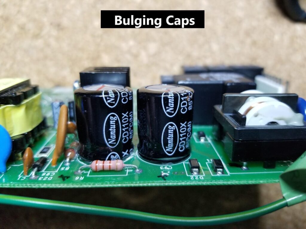
Failing aluminum electrolytic capacitors can have significantly adverse effects on electronic circuits. Most technicians have seen the tale-tell signs – bulging, chemical leaks, and even tops that have blown off. When they fail, the circuits that contain them no longer perform as designed – most often affecting power supplies. For example, a failing capacitor can affect the DC output level of a DC power supply because it can’t effectively filter the pulsating rectified voltage as intended. This results in a lower average DC voltage and causes a corresponding erratic behavior due to unwanted ripple – as opposed to the expected clean DC voltage at the load. For example, Figure 2 below shows a healthy linear power supply. As you can see, the output (Green Line) is a relatively clean DC voltage with very low ripple. Ripple is the unwanted AC component that the capacitor is intended to filter or (smooth) out. On the rising edge of the rectified waveform (in purple), the capacitor charges. On the falling edge, the energy stored in the capacitor supplies enough voltage to the load to tie it over until the next rising edge.
Be sure to subscribe to our Youtube Channel!
For tons of videos on electrical and electronics diagnostics, practical electrical theory, and field-technician resources, click the picture below or this link here: https://www.youtube.com/@TheTechCircuit?sub_confirmation=1
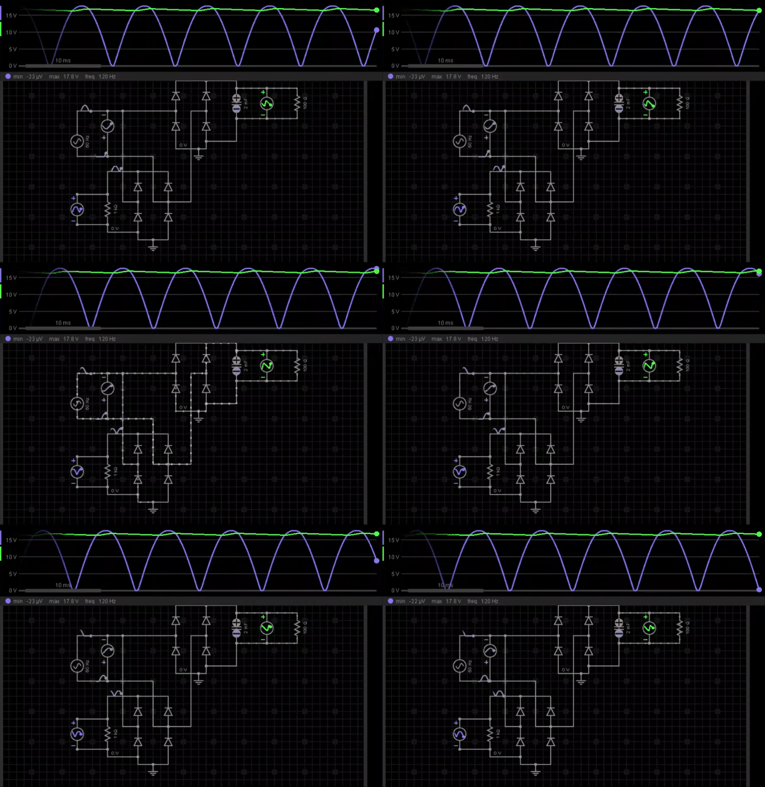
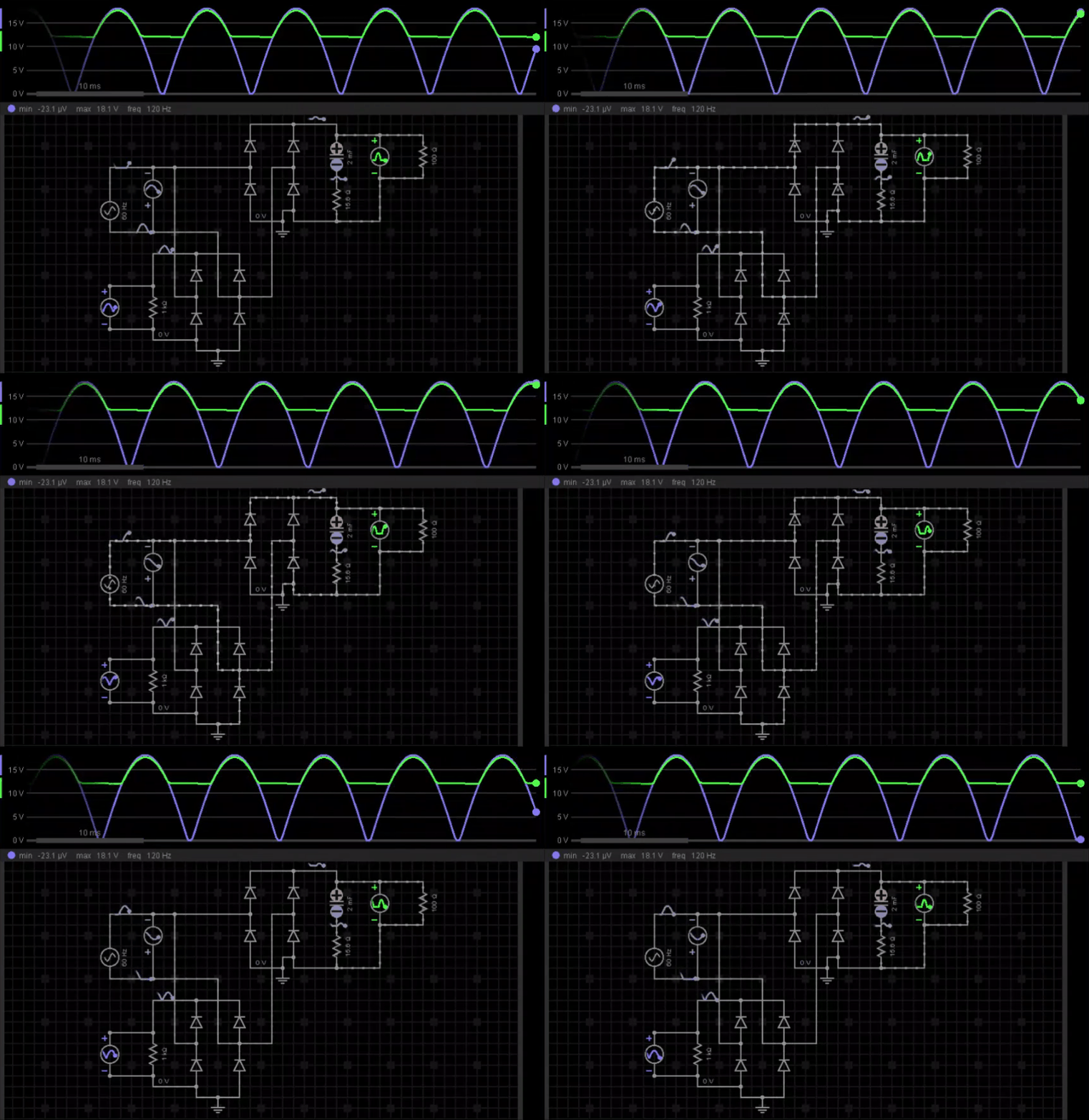
Figure 3 shows the same power supply with a failing output filter capacitor. Because the ESR (Equivalent Series Resistance) of the capacitor has increased, the circuit no longer performs as designed. This causes two things to happen. It is as if an extra resistor was placed in series with the capacitor. Also, the surface area of the capacitor plates has effectively decreased – reducing capacitance. So instead of filtering out the unwanted AC ripple, that ripple appears across both the newly introduced resistive component within the physical capacitor as well as the effectively reduced capacitance. This results in an unclean output voltage (Green Line) with a lower than required average DC level to the load. So when the rectified voltage (in purple) rises, the capacitor is unable to store enough of that energy – so that on the falling edge, the output voltage (in green) just drops off to a reduced level.
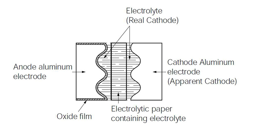
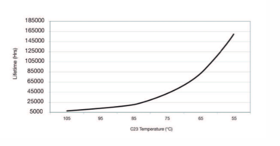
Replacing the capacitor usually resolves this issue. The circuit can once again function as designed – filtering out the unwanted ripple voltage and delivering a clean DC voltage to the load. But why do these caps fail? What can be done to prevent this? How do you prevent this from recurring? For one, electrolytic capacitors have a limited life. Most aluminum electrolytic capacitors are guaranteed to last 1000 – 10,000 hours at their rated temperature, depending on the capacitance and voltage. For power supplies that run 24/7 (such as those in appliances that supply power to the “on” button), this translates to 42 days to 1 1/2 years. The overall life also depends on the load the power supply is under, the ambient temperature around the capacitor (they can last exponentially longer hours as operating temperature decreases), and the duty cycle of use (how any hours/day the supply is energized). High operating temperature is one reason that electrolytic capacitors are one of the most commonly failing components in electronics. Figure 4 shows how an electrolytic capacitor is constructed.
*If you are benefiting from The Tech Circuit, please consider donating HERE*
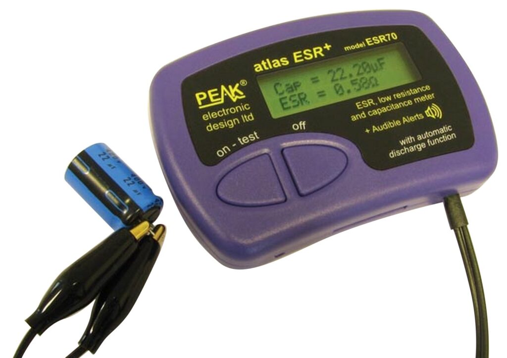
Recommended ESR Tester – CLICK THE IMAGE TO LEARN MORE
For the sake of this article, the part that causes an electrolytic capacitor to fail most often will be highlighted. Essentially, the capacitor consists of two pieces of foil insulated from each other and wound together. The positive (anode) side of the foil, which is connected to the capacitor’s positive lead, is insulated by a thin chemical film. This separates the positive plate from the negative plate. The negative plate consists of highly conductive liquid called an electrolyte. The cathode foil and insulated anode have rough surfaces that create a large surface area. This liquid fills the gaps on these rough surfaces – effecting a larger capacitance than with smooth surfaces and no liquid electrolyte. When the capacitor is new, this liquid has a very low resistance. As time goes by though, the liquid electrolyte evaporates. This causes the resistance to increase and a voltage drop to appear between the negative plate and negative lead.
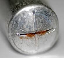
The extent of this voltage drop is also frequency-dependent, since – as the negative plate “dries up”, the capacitance effectively decreases and the capacitive reactance (sometimes called AC resistance) increases. When this happens, the current through the capacitor and the increased voltage drop across the electrolyte results in increased power dissipation and heat. This further causes the electrolyte to evaporate. A runaway effect occurs – more heat, more evaporation – until the liquid boils/evaporates out. At this point, the electrolyte’s effective resistance is very high – causing a high ESR. Figure 5 shows a capacitor that has released its electrolyte.
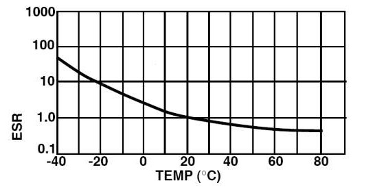
Operating temperature greatly affects an electrolytic capacitor’s performance. Generally, if you lower the temperature, the ESR goes up. This is because the ions that move the charge through the electrolyte are less mobile. The higher the temperature, the more fluid the electrolyte is and the more mobile the ions are. Technicians may have noticed that a circuit board may fail when cold but works when warmed up. This is because the capacitors’ ESRs all reduce when warm. Circuit boards in refrigerators and freezers may prematurely fail because of this. Figure 6 shows the inverse relationship between operating temperature and ESR.
This is not to be confused with how heat affects capacitors. High operating temperature can, over the long term, cause the electrolyte to more quickly evaporate or boil out.
Disclaimer
This blog is intended for experienced or supervised technicians. Always take appropriate safety precautions when dealing with live circuits. For informational purposes only. Utilize the concepts in this blog at your own risk. The Tech Circuit or Steve Morrison assumes no responsibility or liability for any errors or emissions in the content of this blog. The information contained in this blog is provided on an as is basis with no guarantees of completeness, accuracy, usefulness, or timeliness. Never attempt to repair circuit boards unless you are directly supervised by a licensed professional engineer and doing so under approved ISO and UL processes.
Remember:
“Diverting 10 min/day of social media time towards learning something new, is 5 hours of newfound monthly knowledge.” – SM
To DONATE to the Tech Circuit – CLICK HERE
Alphabetical Links to all Tech Circuit Articles and Blogs – CLICK HERE
Links to all Tech Circuit Cheat Sheets/Field References for Appliance/HVAC Techs – CLICK HERE
For additional electrical and electronics learning material for field techs, visit our homepage at http://www.TechCircuit.org or our Facebook group at https://www.facebook.com/groups/746823709133603.
We are a participant in the Amazon Services LLC Associates Program, an affiliate advertising program designed to provide a means for us to earn fees by linking to Amazon.com and affiliated sites.
