Should Appliance and HVAC Technicians Learn about Electricity?
If you work on appliances and HVAC systems, you will ultimately encounter symptoms caused by electrical and electronics failures. This does not just happen occasionally, but on a regular basis. You don’t want to be the technician that gets stuck because they cannot address such issues due to either apprehension or lack of basic electrical troubleshooting knowledge.
There are fundamental concepts that every technician can and should possess that will help him/her tackle the inevitable failed electrical/electronic component or subsystem. The primary concept is Ohm’s Law. Many technicians dismiss it because they feel they rarely need it. I believe one of the reasons for this is that they either don’t understand it or simply work around it – based on simple experience (parts changing) or pattern recognition (I’ve seen this before – so let’s replace this). Well that has it’s value. However, understanding how electronics works, allows you to mine those deeper veins of gold that you have may have forgone in favor of simplicity or just staying in that “comfort zone”.
Let’s consider some examples how such knowledge can change the course of how you address these failures.
Case 1: A high impedance voltage source.
You’re called out on a classic Whirlpool electric dryer. The symptom is no heat. You first check the receptacle at the wall with your multimeter and get 240V. You then move on to the next step – you remove the back and do continuity checks on the element, thermal cutoffs and cycling thermostat. You get continuity on everything and now realize this isn’t going to be a slam-dunk repair. You then check current at either L1 or L2 with a clampmeter and get 3 amps. Realizing this must be L1 because you are measuring the motor current, you wiggle the timer – looking for that burnt timer contact – and nothing. The heater contact in the timer could still be bad, so you go on to the next step.
Ok. Now it is time to do voltage checks. Using L1 as a reference, you check the voltage at the L1 side of the element (side with thermal cutoffs). You are expecting 240V and get 0V. Ok, this means that 240V is not being dropped across the timer. Maybe it’s the centrifugal switch? Ok. Lets use L2 as a reference now and put the other lead on the heating element (centrifugal switch side). We should get 240V if the centrifugal switch is bad right? You get 0V. Ok, what’s going on? Out of frustration, you measure the voltage across the element and get 5V. Now you realize what you forgot to do.
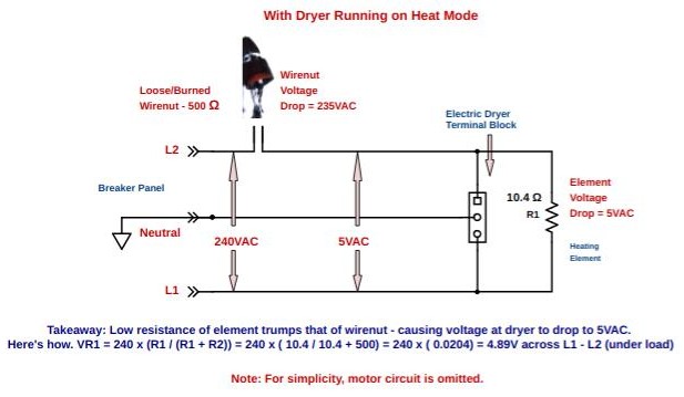
You were previously taught that if you suspect a voltage problem – check it under load. Why is this though? What’s really happening? Understanding how the “voltage divider” works in this case should have instinctively led you to check it either with the dryer running on heat or with a LoZ meter. Figure 1 below shows the equivalent circuit and calculates the voltage across the heating element for the electric dryer connected to a 240V circuit with a loose wire-nut in an attic junction box.
Case 2: Electric range control panel only lights up when burner turned on.
You go out on this call and see that yes, the customer is right. No control panel display, but when you turn on any burner, the display lights up. You check the burner with your infrared thermometer and find that it only increases by a few degrees. Ok. what’s going on here? If you’ve never seen this problem before, you may be completely lost. This is not how you want to present yourself to the customer. There is a very logical explanation for this though.
Having a fundamental knowledge of Ohm’s Law, current flow, and voltage drops, may have led you to conclude that the control panel was somehow getting its voltage supply through the burner. You would be right. Your range is missing the L1 power leg. L1 is needed to supply the control panel. When the burner is turned on, L2 will appear where L1 was and seek a return path through the control panel to Neutral.
The impedance (or effective resistance for the sake of simplicity) of the control panel is very high as compared to the burner. In fact, given the typical current draw of a control panel, its impedance is around 300 ohms. An 8″ burner though, typically has a resistance of about 26 ohms. Having a good feel for electronics will immediately tell you that the voltage divider between the two favors the control panel. Why? There will be a fixed amount of current flow through the burner and the control panel to Neutral. The voltage across both is then dictated by their resistance. The higher the resistance for a given current, the higher the voltage. In fact, in this scenario, the control panel still gets 110V – plenty enough to function. Remember – “The highest resistance gets the most voltage”
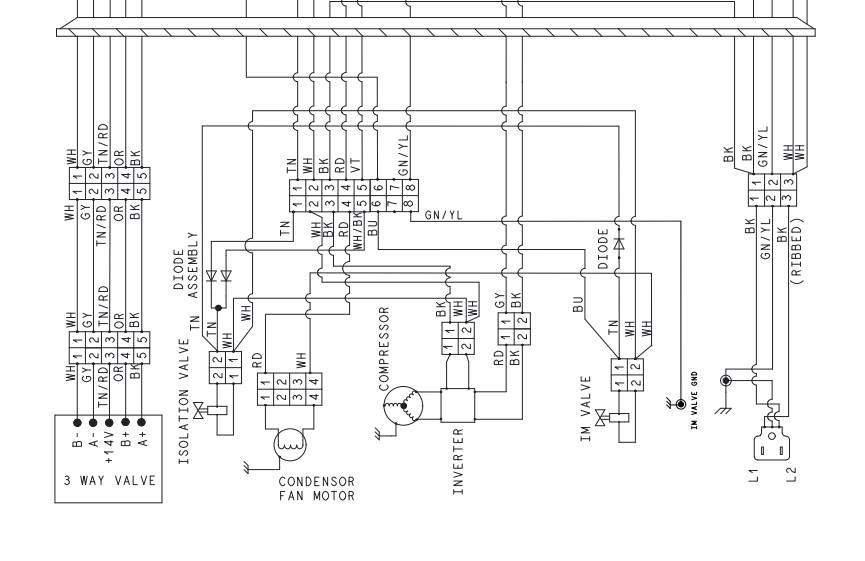
If you look at the schematic in Figure 2, you will see how L2 travels through the burner and effectively replaces L1 by supplying 110 volts on the right side, with respect to Neutral. Will the bake and broil functions work when you select them? No. Since L1 is missing, the elements cannot complete a circuit between L1 and L2.

Case 3: Bake relay won’t close and turn element on.
You go on a “no bake” call for an electric oven. From the control panel, you put it into bake and hear the relay’s clicking, but no bake. The element ohms out and there are no apparent wiring or voltage issues. You double-check and yep, there is no voltage across the bake element.
Ok. Time to put your meter on the board. You locate the DLB (double line break) relay. You check the voltage across the contacts and get 0V when in bake. Not accounting for contact resistance, you know this is good because your electronics background dictates that for whatever amount of current should be passing through the circuit, you should have close to a 0V drop across 0 ohms. Essentially all of the voltage should be across the bake element. You check the Bake relay contacts and get 240V. Ok, so this isn’t right. There should also be 0V across them as well. So we’ve localized the issue. Either the bake element is not closing or the contacts are completely trashed – because they are open when they should be closed.
Next step. You check the voltage across the Bake relay coil and get 12VDC. Since the relay is rated for 12VDC, it should be closing right? So you have one of two causes. Either the relay contacts are so bad that they have no continuity or the relay coil is open. You have determined this because your knowledge of electronics tells you that you can’t have 240V across closed bake contacts OR you can’t have 12VDC across the relay coil and not have enough magnetic pull to close the relay. So since an open relay coil will cause the contacts to remain open – you test that first – and find that yes, you have infinite resistance. You replace the board and you’re done.
These are just a few examples of how that foundational knowledge can help you in the field. Some techs say that they rarely need to refer to “Ohm’s Law”. While that may be true – I think they would use it more often if it came easy to them – rather than having to look it up or call someone that does. I use that knowledge almost every day – because everything we work on is utilizing it (sometimes 24/7) – and any electronics related failure is connected to it in some way.
Summary
Learning about electricity is largely about academics. Academics can sometimes be inconvenient and tiresome. Think about how much daily time though, we spend doing things that could otherwise be allocated towards learning something new. You will more easily get through elecrical diagnosis if you have a solid academic foundation that will help you “connect the dots” when in the field. “Book knowledge” combined with experience is one of the best tools a technician can have to their avail.
Disclaimer
This blog is intended for experienced or supervised technicians. Always take appropriate safety precautions when dealing with live circuits. For informational purposes only. Utilize the concepts in this blog at your own risk. The Tech Circuit or Steve Morrison assumes no responsibility or liability for any errors or emissions in the content of this blog. The information contained in this blog is provided on an as is basis with no guarantees of completeness, accuracy, usefulness, or timeliness. Never attempt to repair circuit boards in appliances or HVAC systems unless you are directly supervised by a licensed professional engineer and doing so under approved ISO and UL processes.
Don’t forget:
“Diverting 10 min/day of social media time towards learning something new, is 5 hours of newfound monthly knowledge.” – SM
To DONATE to the Tech Circuit – CLICK HERE
Alphabetical Links to all Tech Circuit Articles and Blogs – CLICK HERE
Links to all Tech Circuit Cheat Sheets/Field References for Appliance/HVAC Techs – CLICK HERE
For additional electrical and electronics learning material for field techs, visit our homepage at http://www.TechCircuit.org or our Facebook group at https://www.facebook.com/groups/746823709133603.
We are a participant in the Amazon Services LLC Associates Program, an affiliate advertising program designed to provide a means for us to earn fees by linking to Amazon.com and affiliated sites.