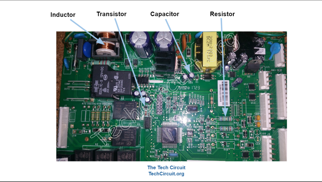
What Resistors, Capacitors, Inductors, Diodes, and Transistors do.
If you work on anything electrical or electronic, you’ve seen these components. What are they used for though – and how do they work? This blog gives you the short answers.
Be sure to subscribe to our Youtube Channel!
For tons of videos on electrical and electronics diagnostics, practical electrical theory, and field-technician resources, click the picture below or this link here: https://www.youtube.com/@TheTechCircuit?sub_confirmation=1
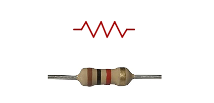
What does a resistor do?
A resistor limits current flow. It is analogous to a bottleneck in a water pipe. Its resistance (R) is measured in ohms – and here are some of its common functions:
- Limits current flow.
- Used with other resistors to split up voltage or current to useful levels (like in voltage or current dividers).
- Provide biasing for transistors and other components.
- It can be used to dissipate power (release energy) in the form of heat. A common electric cooktop burner is a resistor. When voltage is applied to that resistor, it gets hot and dissipates heat. In this case, the resistor is used to take some of the power generated at the source (power station) and outputs it in the form of heat on your cooktop.
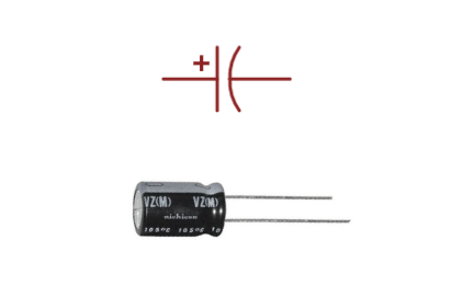
What does a Capacitor do?
A capacitor stores electrical energy. It’s ability to do so is measured by its capacitance in Farads (F). Microfarads (uF) is a more common unit, because a Farad is quite large. A Microfarad is one millionth of a Farad. Since they store energy, they are often used in power supplies to store and release energy from a pulsating DC voltage to a load so that the voltage at the load is relatively smooth DC. They are also commonly used to series pass AC current, but block DC current, such as in amplifiers. Since they store and release energy, they can also cause current to occur before voltage, which is useful for causing a rotating magnetic field in single phase induction motors. Here are the common features and functions of capacitors.
- They store energy in the form of a charge on two plates that are insulated from each other, but are in close proximity.
- They resist changes in voltage.
- They pass AC current, but do not pass DC current.
- They are commonly used to filter waveforms.
- They cause an often useful delay between current and voltage.
- They are used to improve the power factor of inductive loads.
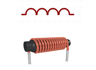
What does an Inductor do?
Inductors store energy in the form of a magnetic field. Their ability to do this is measured in Henrys (H). They resist changes in current, which makes them useful for noise filters and storing energy. The windings of a transformer and the stator of a motor are both inductors. The magnetic fields created by them cause voltage to appear on the secondary of a transformer, and cause induction motor armatures to turn. When you try to change the current though an inductor, it creates an opposite voltage in an effort to maintain that current. Inductors also delay current through them. These facts are exploited in many ways in electronics. Here are some features and functions of inductors:
- They store energy via a magnetic field.
- They resist changes in current.
- They freely pass DC current, but impede the flow of AC current.
- Much like capacitors, they commonly used to filter waveforms, but in an inverse manner.
- They cause an often useful delay between voltage and current.
- Can be use to develop large voltages by rapidly changing the current through them.
- Since inductor current vs. voltage is delayed, inductance is used in a relative way in motor windings to cause rotating magnetic fields (commonly found in split-phase dryer motors).
What does a Diode do?
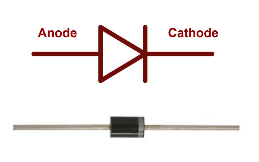
A diode is a semiconductor device that only allows current to flow in one direction. When it does so, it is know as being “forward-biased”. In this condition, the anode is more positive than the cathode. Per the symbol below, the anode is the back side of the diode and the cathode it the pointed side. It tends to form an arrow that denotes the direction of (conventional) current flow. When, however, the cathode (pointed side), is more positive than the anode, current will not flow. This condition is known as being “reverse-biased”. This behavior is subject to limitations, however. When forward biased, all diodes exhibit a voltage drop. A typical voltage drop for a silicon diode is 0.7v, meaning that when the diode is forward biased and passing current, it requires that 0.7v is lost across it. Another characteristic of diodes is that they all have a peak reverse voltage, meaning that at some point, enough reverse voltage will cause the diode to break down and start conducting in reverse. A common IN4001 diode has a peak reverse voltage of 50v. An IN4004, on the other hand has a 400v peak reverse voltage. So it is easy to choose the diode for your task at hand. Zener diodes are specialized diodes that have a deigned peak reverse voltage drop and are intended to be reversed biased, so as to create a voltage reference of that peak reverse value. Diodes are useful for:
- Rectifying AC voltage
- Polarity protection
- Clamping voltage spikes across relays and other inductive loads
- Voltage regulation (in the case of Zener diodes).
What does a Transistor do?
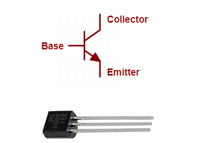
The common bipolar transistor is like a valve which is used to control current flow. It is one of the primary descendants of the old-time vacuum tube. It has three terminals – the base, collector, and emitter. The base is like the handle of a faucet, and used to control the current flow. The collector is where the current enters the transistor, and the emitter where it is exits. The base can control large amounts of current through the collector and emitter, by using a very small amount of current. The ratio of this ability is called the gain. Many general purpose transistors can be used to control a 100-fold or greater amount of current from the small amount of current at its base. Here are some of the many uses of transistors:
- Regulate and control current flow
- Electronic switches (like to drive relays or to pulse transformers in switched mode supplies)
- Amplifiers
- Voltage regulators
Test your Practical Knowledge of Electronic Components!
Understanding Basic Electronic Components
Select the best answer for each question.
Summary
You’ll see resistors, capacitors, inductors, diodes, and transistors on almost every control board you encounter. They are ubiquitous in electronics. It is important to understand their purpose, and how they are used in electronics if you are troubleshooting or modifying any boards that utilize them.
Disclaimer
This blog is intended for experienced or supervised technicians. Always take appropriate safety precautions when dealing with live circuits. For informational purposes only. Utilize the concepts in this blog at your own risk. The Tech Circuit or Steve Morrison assumes no responsibility or liability for any errors or emissions in the content of this blog. The information contained in this blog is provided on an as is basis with no guarantees of completeness, accuracy, usefulness, or timeliness. Never attempt to repair circuit boards in appliances or HVAC systems unless you are directly supervised by a licensed professional engineer and doing so under approved ISO and UL processes.
Don’t forget:
“Diverting 10 min/day of social media time towards learning something new, is 5 hours of newfound monthly knowledge.” – SM
To DONATE to the Tech Circuit – CLICK HERE
Alphabetical Links to all Tech Circuit Articles and Blogs – CLICK HERE
Links to all Tech Circuit Cheat Sheets/Field References for Appliance/HVAC Techs – CLICK HERE
For additional electrical and electronics learning material for field techs, visit our homepage at http://www.TechCircuit.org or our Facebook group at https://www.facebook.com/groups/746823709133603.
