What is Pattern Recognition as it Applies to the Service Industry?
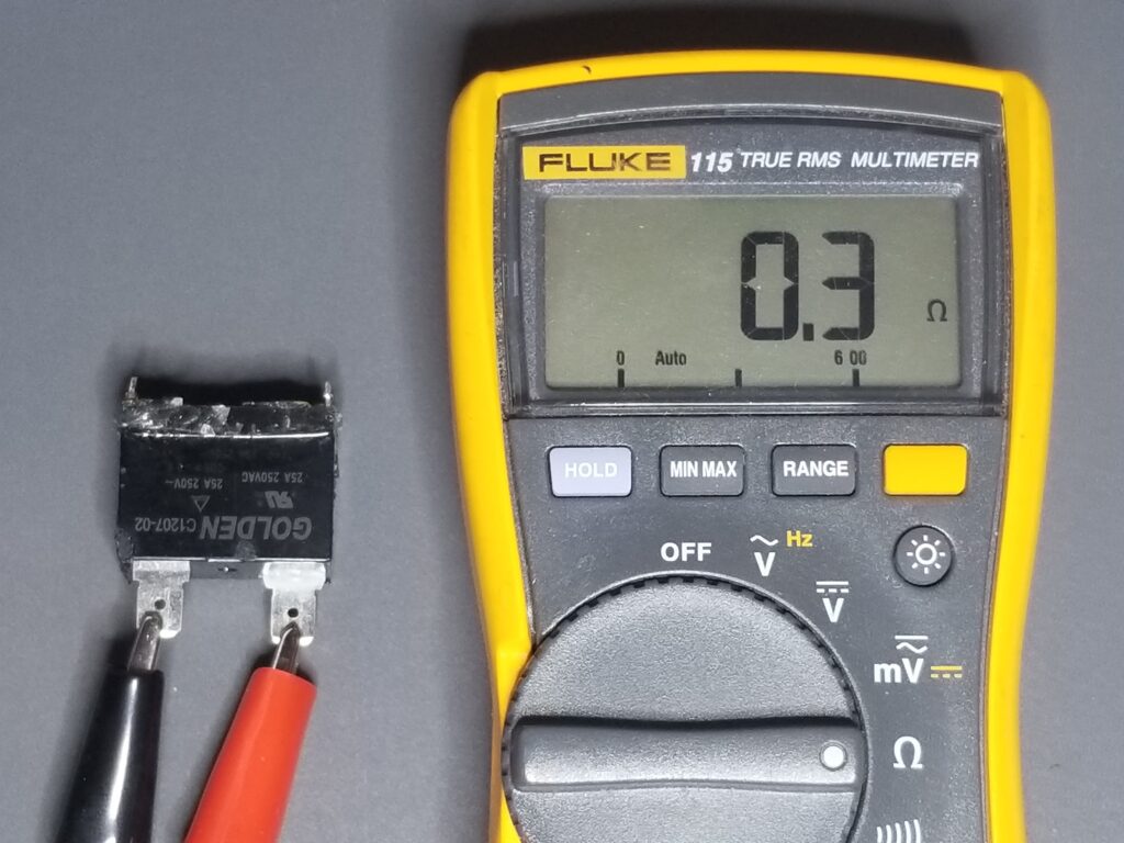
Pattern Recognition, or “PR”, as it applies to the appliance and HVAC repair industry, is simply noticing similarities between symptoms and causes. If 7 out of 10 times, an electric dryer is found to have “no heat”, and the element is open, PR will deem the element to be the most likely cause for that model going forward. Similarly, if a dryer runs continuously (even if the control panel is off), you may know without having to diagnose the unit, that it has a stuck motor relay.
How Useful is Pattern Recognition?
PR is invaluable in the repair industry, and an integral part of Technicians’ assessment methodology. In fact, experienced Technicians often know what part they need to replace even before they arrive at their service call. It also helps dictate diagnostic trees and flowcharts.
Diagnostic vs. Pattern Recognition
PR wouldn’t exist, however, without someone initially diagnosing and resolving a problem. It had to start somewhere. The general term “diagnostics” in this article refers to the systematic assessment performed to identify the cause of a failure. Similar to PR, having diagnostic capability is equally important. One must possess the ability to thoughtfully and logically navigate the diagnostic process to uncover the underlying causes. Additionally, like PR, this diagnostic capability is developed through experience. However, unlike PR, it heavily relies on academic knowledge. One must understand how systems work, the components that comprise the system, and the likely symptoms resulting from specific component failure.
Key Basic Concepts of Electrical Diagnostics
Appliance and HVAC Technicians will inevitably encounter electrical problems that require diagnosis. To effectively diagnose these circuits, however, Technicians must have a solid understanding of fundamental concepts. The following are the bare-minimum “must-know” electrical rules summarized below.
Highest Resistance Wins the Voltage
One of the most important basic electrical concepts that Technicians should know (and I cannot stress this enough) is that in a series circuit, the highest resistance (or impedance) among two or more loads receives the highest voltage. Surprisingly, many Technicians are unaware of this concept, which actually explains most failures caused by high-current connections becoming loose (either mechanically or due to heat). These failures result in a voltage drop, subtracting from the required voltage across an element, for instance. This concept also applies to open components such as a switch, a broken wire, or a relay contact, which exhibit infinite resistance. In a series circuit, such an “open” component will undoubtedly have the highest, if not the entirety of the voltage drop across it.
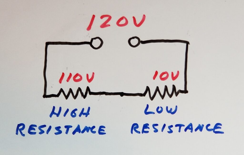
Voltage Across Loads Adds up to the Total Voltage
Inextricably tied to the above concept is the basic rule, rooted in Ohm’s law, that for resistive loads (such as elements and even loose connections), the voltage across each load in a series circuit sums up to the supply voltage. This explains the scenario mentioned earlier, where a loose terminal block depletes the voltage intended for a heating element. In this case, the supply voltage (typically 240v) subtracted from the voltage across the terminal block leaves very little voltage for the element (often close to zero volts).
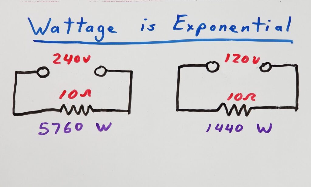
Wattage or Heat Output is Exponential
Here’s a non-intuitive fact that Technicians encounter regularly: doubling the voltage results in quadrupling the wattage (and heat output) of an element. The inverse is also true. If the voltage across an element is halved, the heat output decreases to 25%. This fact is particularly relevant when dealing with 240v appliances that have lost one voltage leg. It directly correlates with and can be easily explained by the “Voltage Across Loads Adds up to the Total Voltage” section discussed earlier. Technicians have encountered and will continue to encounter numerous examples of this phenomenon throughout their careers.
Avoid Neutral in 240v Circuit Diagnostics
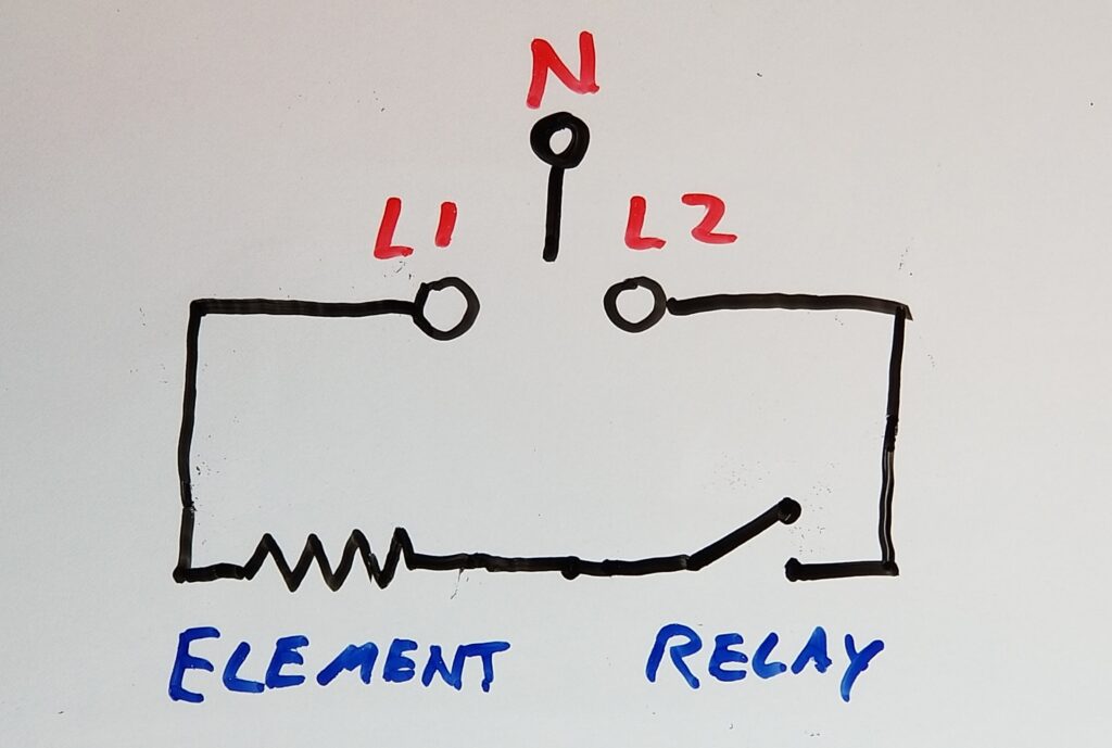
How often have you heard a Technician in social media groups state, “I have 120v on each side of the element, but it won’t heat,” or some variation of that? The issue here is that they are likely referencing their readings from Neutral. I have reminded many Technicians that “Neutral is not part of the 240v circuit,” as shown in the diagram below. In most cases, Neutral is used as a return path for 120v circuits in appliances such as motors, heating elements, and control boards.
However, when diagnosing 240v circuits, the voltage source is derived from the difference between L1 and L2. Neutral is not involved and is hardly relevant. In fact, referencing Neutral can provide incorrect information because your meter cannot determine, when referencing Neutral, which 120v reading corresponds to L1 or L2 due to their opposing polarities. Therefore, when testing voltage across a 240v load, it is important to reference either L1 or L2 only.
It’s important to note that there is an exception when referencing Neutral is appropriate: when determining whether L1 or L2 has been lost at a wall receptacle or junction box. However, this should only be done when the appliance is disconnected to avoid back-feed through one of the appliance loads. Otherwise, once you have established that L1 and L2 are “solid”, and reaching the appliance, using L1 or L2 as a reference is all you need, following specific diagnostic techniques described in this article.
Coils Reduce AC Current
Coils, such as those found in solenoids (water valves), HVAC contactors, and even motors, primarily behave as inductors during normal operation. What does an inductor do? Simply put, it opposes and reduces AC current. This means that the resistance you measure when “ohming” out a coil is not the same “opposition to current flow” that the AC voltage will encounter when applied to that coil. That opposition, combined with the coil’s measured DC resistance, is known as impedance (also measured in ohms) and is typically much higher than the measured resistance. Consequently, the current drawn by the coil when connected to an AC voltage will be significantly lower than if it were connected to a DC voltage.
Another important piece of information that Technicians should be aware of, but may not know, is that when a solenoid core, such as a water valve plunger or contactor core, becomes stuck and is unable to fully insert itself into the center of the coil, the current passing through that coil is significantly higher than usual. This is due to the reduced inductance caused by the absence of the core. This phenomenon can explain instances of coil “burn out” or melting in appliances like refrigerator cube solenoids and HVAC contactors. Understanding this aspect is valuable knowledge for Technicians in their line of work.

Beyond the Basics – Advanced Electrical Concepts
For more advanced concepts, such as troubleshooting circuit boards, Technicians may find themselves relying heavily on PR as their primary approach, often replacing commonly failing capacitors and relays. While this method can be useful and profitable, it can also be limiting. Technicians will inevitably encounter situations that require on-board circuit diagnosis. Without a solid foundation in electronics, they may hit a diagnostic brick wall, which can be particularly problematic when aiming for first-call completes (FCCs) or when dealing with non-available (NLA) boards.
However, by persistently pursuing continued education in electronics, Technicians can gradually enhance their understanding of control-board topologies and circuits, and improve their diagnostic abilities. Here are a few advanced concepts that Technicians should strive to acquire knowledge in when considering board repair:
- The function of commonly found components on boards – (SEE THAT HERE)
- Power supply circuits – (LINK TO POWER SUPPLY BASICS HERE)
- Relay circuits – (LINK TO RELAY CIRCUIT BASICS HERE), (LINK TO EASY RELAY TESTING HERE)
- How to identify and resolve capacitor issues (LINK TO CAPACITOR FAILURES AND CIRCUITS HERE )( LINK TO CAPACITOR TESTING AND REPLACEMENT CHEAT SHEET HERE
- How to test semiconductors (LINK TO SEMICONDUCTOR TESTING CHEAT SHEET HERE)
Limiting Oneself to Pattern Recognition
Technicians can “get by” by relying solely on PR if they choose to do so. However, being confined to a patternistic approach of simply changing parts is inherently limiting and challenging to sustain. They will frequently encounter situations where they hit dead ends that not only waste their time but, more importantly, are not in the best interest of their customers. The reality is that, in the grand scheme of things, they’ll struggle to be an effective Technician who adds significant value to both the customer and the industry as a whole.
Diagnostics and Pattern Recognition are Symbiotic
As mentioned, PR is an invaluable tool for repair Technicians. It enables them to “pre-diagnose” cases over the phone and often leads to swift and decisive resolutions in the field. However, in practical terms, PR cannot exist in isolation. It must be complemented by competent diagnostic capabilities, which, when combined, promote thorough and effective solutions to the cases Technicians encounter. Nonetheless, the learning process never ends. Continuing education in diagnostic techniques and understanding of how systems work is indispensable to achieving this goal.
Don’t forget:
“Diverting 10 min/day of social media time towards learning something new, is 5 hours of newfound monthly knowledge.” – SM
To DONATE to the Tech Circuit – CLICK HERE
Alphabetical Links to all Tech Circuit Articles and Blogs – CLICK HERE
Links to all Tech Circuit Cheat Sheets/Field References for Appliance/HVAC Techs – CLICK HERE
For additional electrical and electronics learning material for field techs, visit our homepage at http://www.TechCircuit.org or our Facebook group at https://www.facebook.com/groups/746823709133603.