Introduction
This blog shows you how to test Zener diodes using a multimeter and a few items that are commonly found around the house or workbench.
Safety
Although the voltages used in the tester we’ll use are relatively low, know that voltages in excess of 30 volts can be a safety issue under the right conditions – particularly if the user’s hands are wet or affected by perspiration. I wore gloves during the demonstration and the attached video, because I’m risk-adverse, and well, you never know.
What is a Zener Diode?
Contrary to a traditional diode, where current is intended to flow in the “forward bias” condition, as shown below, a Zener diode is intended to pass current in the opposite direction – making use of its reverse breakdown voltage. All diodes have such a voltage. However, Zener diodes are designed to have a very specific reverse breakdown voltage. By the way, the images and content of this blog reflect “conventional current flow”.


Be sure to subscribe to our Youtube Channel!
For tons of videos on electrical and electronics diagnostics, practical electrical theory, and field-technician resources, click the picture below or this link here: https://www.youtube.com/@TheTechCircuit?sub_confirmation=1

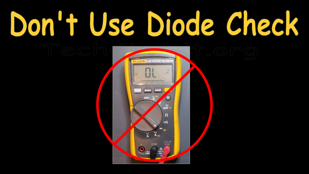
Don’t use the Diode Check Function
You won’t use the diode check function when testing Zeners. The diode check function of most multimeters provides less than 3 volts of bias. The Fluke multimeters top out at 2.0V on the diode check’s range. Instead, you’ll use the DC voltage testing mode of the meter and provide a current-limited voltage source that is connected across leads.
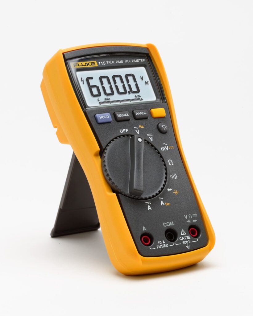
Click Here to Purchase the Fluke Multimeter
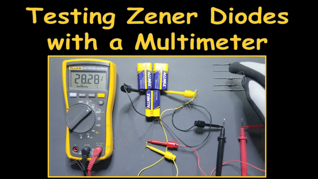
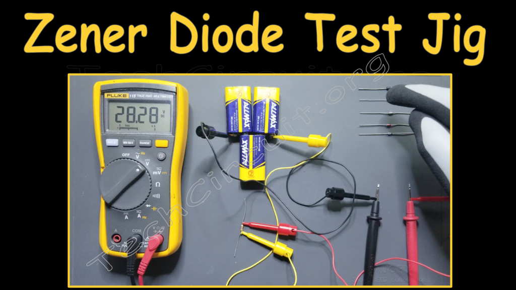
The Simple Tester
The tester consists of a voltage source (three 9V batteries in series), and a current limiting resistor of 4.7k ohms. This limits the current through the Zeners to no more than 9V/4.7k, or 2mA. It is enough current, however, to determine the reverse breakdown voltage of Zener diodes within the range of 1V to 25V. Below is a picture of the actual test jig, and following, is the schematic for it. The full series voltage appears across the meter until you are testing a diode with the leads. Then the voltage will drop to the value of the diode’s reverse breakdown voltage.

Testing Four Mystery Diodes
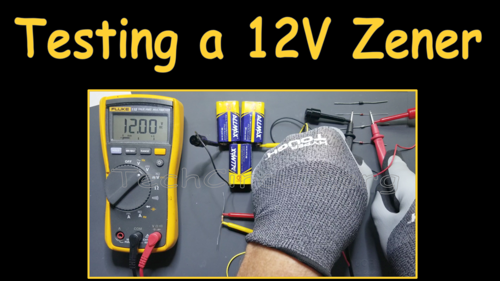
In the demonstration, we tested several mystery diodes (see the embedded video at the end of this blog). The tester worked great for determining the voltage of each. Following is a picture of testing a 12V Zener diode – the tester of which, hit it right on the money.

Open Zener Diodes
Unlike most diodes, which tend to “short out” when they fail, Zener diodes commonly fail in the open state. If you connect the tester to a diode and get no reduction in voltage, the diode is either open, or has a reverse breakdown voltage greater than your test voltage.
Video Demonstration on Testing Zener Diodes
Conclusion
Testing Zener diodes is easy. You only need a current-limited voltage source as described in this blog, and any basic multimeter. You won’t use the diode-check function – so your multimeter won’t even need that. So if yo want to find out what the values of all those Zeners in your bin, you can quickly and easily test, and categorize them.
Disclaimer
This blog is intended for experienced or supervised technicians. Always take appropriate safety precautions when dealing with live circuits. For informational purposes only. Utilize the concepts in this blog at your own risk. The Tech Circuit or Steve Morrison assumes no responsibility or liability for any errors or emissions in the content of this blog. The information contained in this blog is provided on an as is basis with no guarantees of completeness, accuracy, usefulness, or timeliness. Never attempt to repair circuit boards unless you are directly supervised by a licensed professional engineer and doing so under approved ISO and UL processes.
Remember:
“Diverting 10 min/day of social media time towards learning something new, is 5 hours of newfound monthly knowledge.”– SM
To DONATE to the Tech Circuit – CLICK HERE
Alphabetical Links to all Tech Circuit Articles and Blogs – CLICK HERE
Links to all Tech Circuit Cheat Sheets/Field References for Appliance/HVAC Techs – CLICK HERE
For additional electrical and electronics learning material for field techs, visit the following links:
Homepage at http://www.TechCircuit.org
Facebook group at:
https://www.facebook.com/groups/746823709133603
Youtube Channel: https://www.youtube.com/@TheTechCircuit
We are a participant in the Amazon Services LLC Associates Program, an affiliate advertising program designed to provide a means for us to earn fees by linking to Amazon.com and affiliated sites.