What is an H-Bridge?
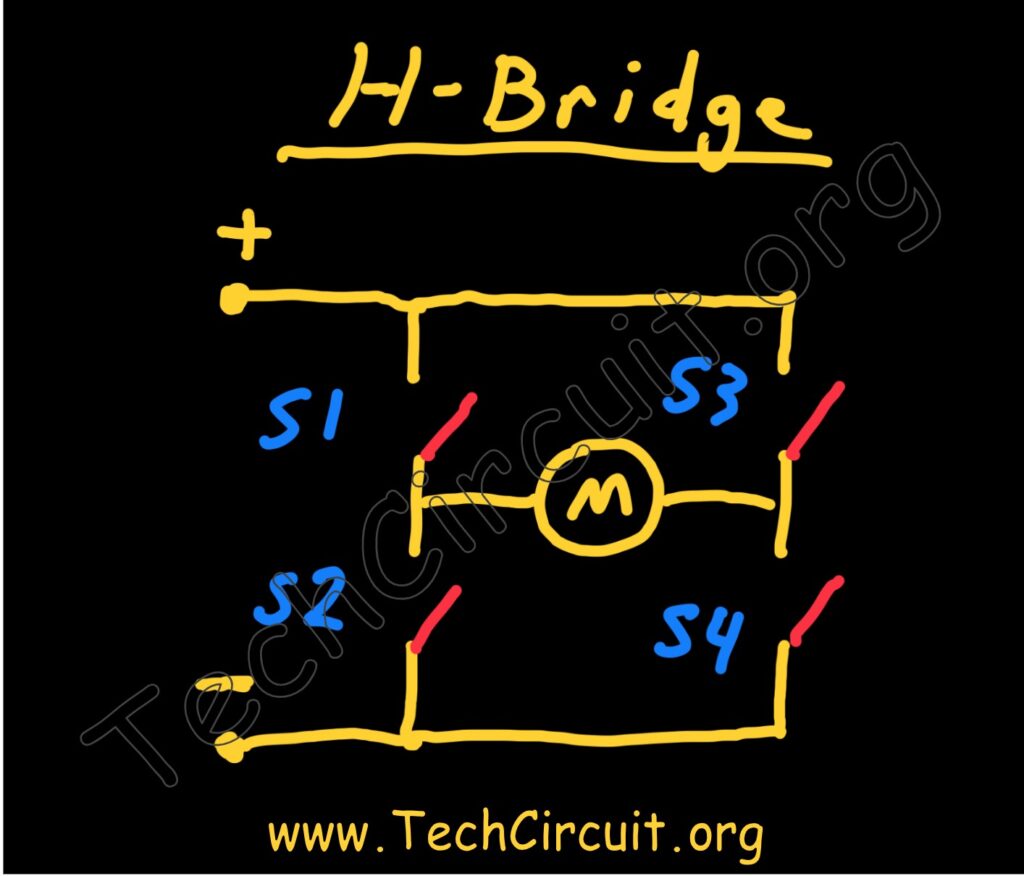
Conceptually, an H-Bridge is just an arrangement of 4 switches configured in such a way as to reverse the polarity of a load. For example, closing switches S1 and S4 will result in a positive polarity to the left of the motor (M). Instead, closing switches S2 and S3 will reverse that polarity. This conceptual arrangement is implemented in practicality by integrated circuits, discrete components, and even relays.
H-Bridges can be used in a plethora of applications, including control of refrigerator dampers, general reversal of DC motors and other loads, and even to effectively reverse the polarity of start windings on induction motors.
Semiconductor H-Bridge
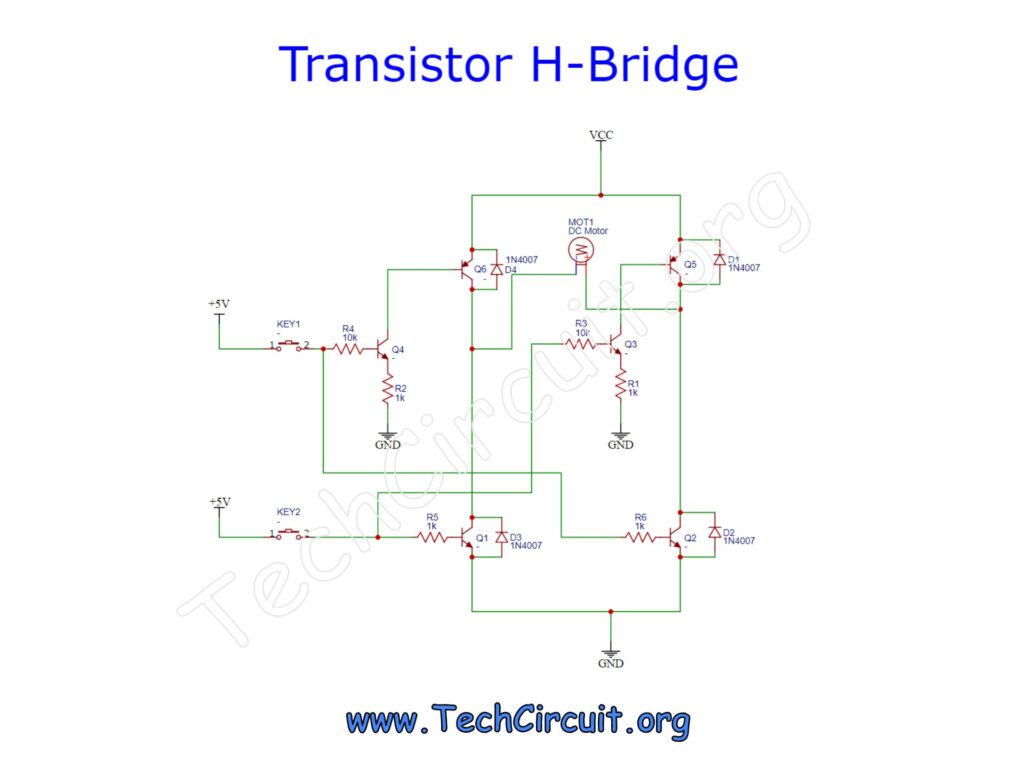
A semiconductor H-Bridge can be constructed using 6 bi-polar transistors. Four transistors (Q6, Q5, Q1, and Q2) act as the respective switches, and two transistors (Q4 and Q3) as pre-drivers. The arrangement below affords a microcontroller the ability to control the three states (Off, Forward, Reverse), with just two control lines, and as well protects the microcontroller from the relatively high voltages and currents of the driver stage.
The switches in the schematic simulate microcontroller output ports. Pressing switch #1 appropriately biases transistors Q6 (via Q4), and Q2 and causes a positive polarity to the left of the motor. Rather, pressing switch #2 causes the opposite polarity through a similar biasing scheme. Both switches being “off”, causes no voltage potential at the motor. Driver transistors Q6, Q5, Q1, and Q2 have inductive clamping diodes to capture spikes from the motor’s collapsing field. In addition to acting as pre-drivers, transistors Q4 and Q1 also provide the necessary logic to the circuit so that two driver transistors can be enabled for one given logic high to the circuit from the microcontroller. One could go a step further and use PWM (pulse width modulation) at the inputs to control the DC motor’s speed (as shown in the demo video below).
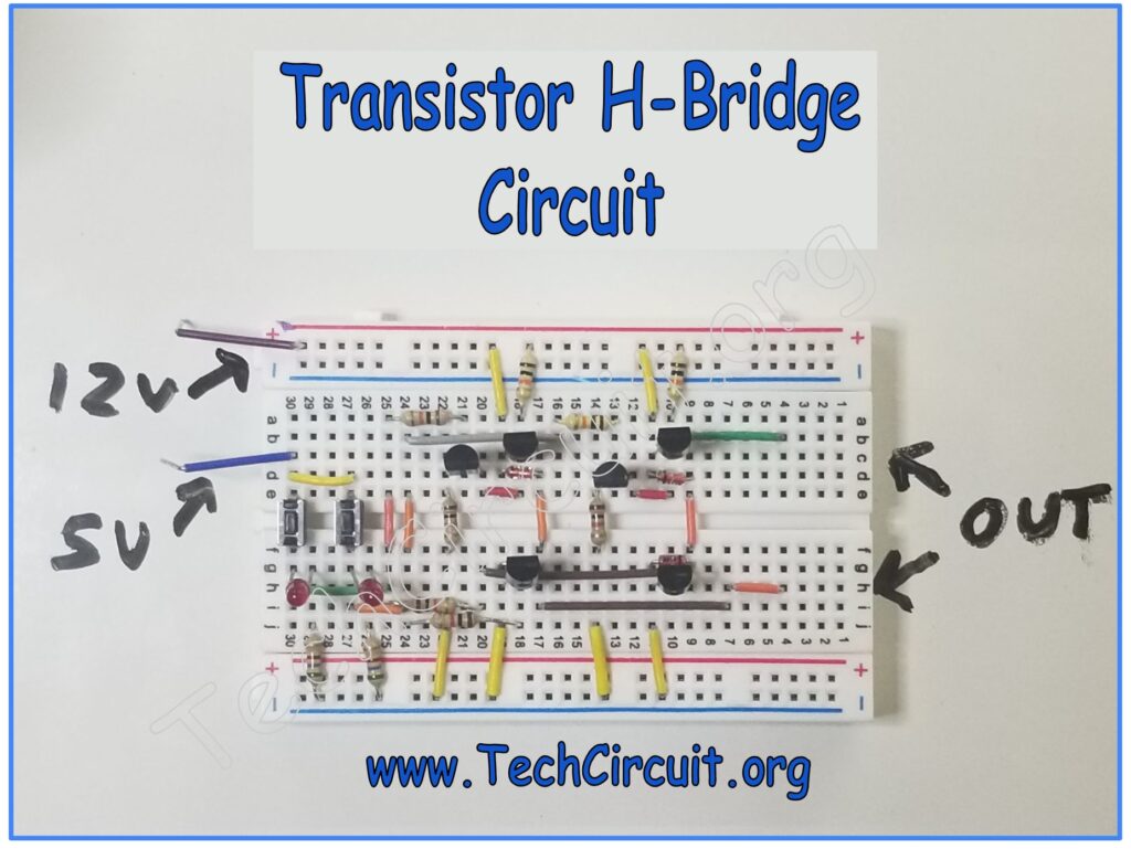
Appropriate resistor values have been used given the currents and gains of the transistors used in the demo. LED indicators on the breadboard are not shown in this schematic, but are easily added using some current-limiting resistors. This is a proof of concept circuit for which appropriately sized/specified components would need to be used for the target application. Any implementation of this circuit should be done at your own risk and discretion.
H-Bridge Demo Video
Here is a video I did that demonstrates the above circuit controlling the polarity of a DC motor and additionally utilizes PWM to control its speed.
Conclusion
An H-Bridge is a handy circuit configuration that is used for many polarity reversal applications. H-Bridges are used in many applications and forms to perform that task. A semiconductor based H-Bridge allows for ease in operation from a microcontroller while protecting said microcontroller from the high currents and voltages involved in the circuit’s driver stage.
Don’t forget:
“Diverting 10 min/day of social media time towards learning something new, is 5 hours of newfound monthly knowledge.” – SM
To DONATE to the Tech Circuit – CLICK HERE
Alphabetical Links to all Tech Circuit Articles and Blogs – CLICK HERE
Links to all Tech Circuit Cheat Sheets/Field References for Appliance/HVAC Techs – CLICK HERE
For additional electrical and electronics learning material for field techs, visit our homepage at http://www.TechCircuit.org or our Facebook group at https://www.facebook.com/groups/746823709133603.