What only Happens in AC Circuits
If you look below the surface of a commonly encountered circuit, you might be surprised about what you find. Most of you know that on many Whirlpool refrigerators, a classic Whirlpool icemaker valve solenoid is energized from the icemaker through a 72 ohm heater. So the solenoid and heater are in series. It may seem like a simple series circuit – but there is a lot more to it.
Here are a few challenge questions that you might think you have the answer to:
- If you test the inlet valve solenoid with a cheater cord and connect 120v directly to it, will that immediately damage the coil? No. This is likely a myth.
- Since 120v is across the series circuit that consists of an inlet valve and the icemaker heater, do the voltages across the two add up to 120v? No. It isn’t intuitive, but they don’t.
- Since the WP W10408179 inlet valve has about 192 ohms of resistance and the icemaker heater has 72 ohms of resistance, the total circuit resistance is 264 ohms. Since current I=V/R, does that mean you’ll have 120/264 or about 0.45 amps drawn when the valve is energized? No. The current is actually much less.
Impedance
If the answers to the above questions don’t make sense to you, you’re probably not considering the often-present AC-circuit phenomenon of impedance. You’ve heard of it – but what is impedance? How does it factor into the circuit and to what degree? It turns out to be significant. In fact, most Technicians regularly encounter it, yet know very little about it.
As the title of this article implies, most of you should probably know the answers to the above challenge questions. However, you shouldn’t necessarily know nor care about the math behind it. That is for those that want to understand the “why”, behind it. However – understanding how things work and why they fail empowers you beyond the point of pattern recognition, and to the realm of thoughtful and effective troubleshooting. So if you want to understand how impedance works, let’s dig into the subject.
Equivalent Circuit of a WP Icemaker Coil
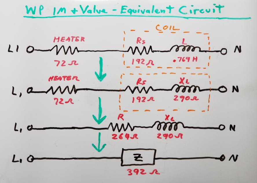
Take a look at the equivalent circuit of WP W10408179 icemaker the inlet valve coil. First, the one thing you can easily measure is the series resistance (Rs), which I found to be 192 Ohms. Further, through measurements and experimentation, I have determined the inductance of the to be 0.769 Henrys. Using an LCR meter such as the DE-5000, makes it easy to check the inductance of coils by the way.
From here, you can calculate the inductive reactance in Ohms – that the coil presents to AC current. The inductive reactance of the coil is simply (2 π f) x L, where π =3.14, f= frequency and L=inductance. The first part of the equation yields (2 x 3.14 x 60Hz) or (377), which is applies to 60Hz circuits and is widely known and used. This is also known as the angular frequency. Anytime you are dealing with 60Hz circuits and you want to calculate inductive reactance (in Ohms), just multiply the inductance by 377. If you ever want to calculate capacitive reactance (in Ohms) for 60Hz circuits, use 1/(377xC).
So to find the inductive reactance of the coil, you have 377 x L or 377 x 0.769H = 290 Ohms. From this result, you might notice that the inductive reactance of the coil is actually higher than the coil’s series resistance of 192 Ohms, which is not unusual.

Total Impedance of the Series Icemaker Circuit with Heater and Coil
Based on that calculation, you can find the total impedance of the icemaker circuit. First, look at the icemaker circuit that the 120V source sees when the icemaker is calling for water. This is shown below. Based on the diagram, you have the heater resistance of 72 Ohms, the coil series resistance of 192 Ohms, and then the inductive reactance of the coil, which we just determined to be 290 Ohms. The two resistances are added (264 Ohms) and then the resulting impedance is calculated. The total impedance (“Z”) of the circuit turns out to be 392 Ohms, which determines the current flow through the heater and coil. Yes, you can now just use Ohm’s Law to calculate the RMS current, except instead of I = V/R, it is I=V/Z. So that gives you 120/392 or about 0.3A, which is much lower than the 0.45A in Question #3.
Wattage of the Coil and Heater
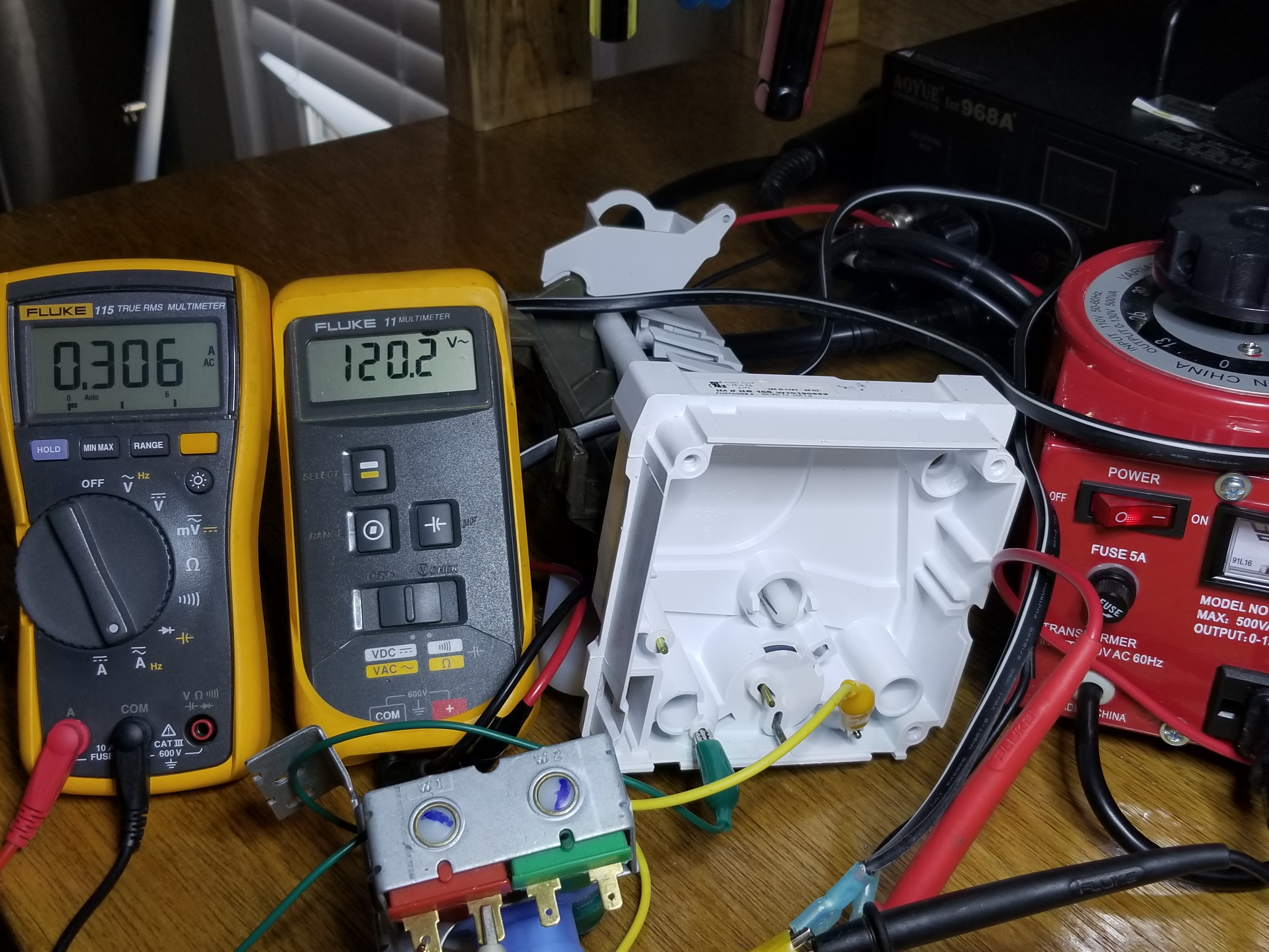
Now that we have the circuit current of 0.3A, we can easily calculate the wattage of the coil (and even the heater). Inductors store and release energy – so they don’t dissipate any power and thus have no “wattage”. The resistive component of the coil is what dissipates power. Remember that we measured 192 Ohms of resistance in the coil. So using the calculated circuit current of 0.3A, the wattage of the coil is simply P = I² x R or (0.3A)² x (192Ω) = 17.28 watts. Likewise, the wattage of the heater in the circuit (when water is being called for) is (0.3A)² x (72Ω) = 6.5 watts. You can also calculate the heater wattage using V²/R and get the same result. In the pictures below, we measured 21.7v across the heater. Plugging that in to the V²/R alternate formula we get the same 6.5 watts. The wattage of the heater during a harvest is much higher, because it is not in series with the valve. It has 120v across it and using V²/R , you’ll find that it produces 200 watts in that mode.
So what Exactly is Impedance?
Like resistance, impedance opposes current flow – but only in AC circuits. Unlike resistors, inductors and capacitors store and release energy, but at different times with respect to each other.
Impedance (“Z”) is a frequency-dependent Pythagorean result of resistance, capacitive reactance (“Xc”), and inductive reactance (“Xl”) – all measured in Ohms. You learned in trigonometry that the hypotenuse of a triangle is the square root of (Adjacent Side)² + (Opposite Side)². Impedance is calculated much in the same way. A graphical representation of impedance, along with its formula is shown below. For the WP inlet valve coil, by the way, the capacitance and resulting capacitive reactance at 60 Hertz is so insignificantly small, it won’t be considered, illustrated, or discussed in this article.
The image below illustrates the concept of impedance (“Z”) as it applies to our example and how the 392 Ohms of impedance was calculated from the circuit’s series resistance (Rs), and its inductive reactance (Xl). You’ll notice is that impedance is the hypotenuse of the triangle, with resistance and inductive reactance being the sides.

Calculated Current Reading vs. Actual Current Reading
As mentioned earlier, from this 392 Ohm result, we calculated the circuit current to be about 0.3A This is what you’d expect to read with an amp-clamp if you were to test it. Below on the left is the actual current reading of the valve in series with a WP IM heater.
Voltage Readings
Below are images of the actual measured voltages – first that across the heater, and then across the coil, which you will see are within less than 1% of the calculated voltages shown next. The 120.2v reading to the right is the source voltage to the series circuit.


Something Just Doesn’t Add Up
Now something very interesting can be illustrated when impedance is involved. You may intuitively think that the voltage across the heater, plus the voltage across the coil would equal 120v (which goes to challenge question #2). While this is true for DC circuits or AC circuits with only resistive loads, RMS series voltages in AC circuits with impedance don’t add up to the source voltage. The diagram below shows that when you use the 0.3A to determine the voltage across the heater and coil, they Do Not add back up to 120v. The impedance of the coil needs to be calculated separately in order to determine the voltage across it. Using the same Pythagorean formula as before, this can be easily done. You’ll see that the impedance of just the coil (as opposed to the entire circuit as above) is 348 Ω . This means that the voltage across the heater should be 0.3A x 72Ω or (21.6v) and the voltage across the coil should be
0.3A x 348 Ω or (104.4v). If you add those together, you see that they do not add up to 120v. That’s ok, and should be expected when impedance is involved.
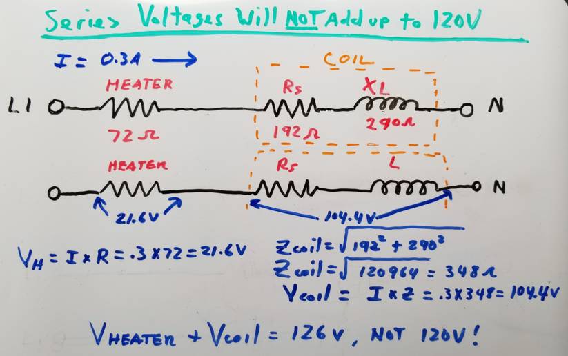
The fact that the series voltages don’t add up to the source voltage answers Challenge Question #2.
How do We get Things to Add Up?
So how do you get voltages in a non-resistive AC circuit to square up with the source voltage? By using the same Pythagorean formula that was used to calculate impedance. Since the coil is a mixture of resistance and inductive reactance, you can’t just drop it into the formula as-is. You have to break it down into it’s constituent parts. So the coil has 290 Ω of inductive reactance, and 192 Ω of resistance. The heater is 72 Ω so you add the resistances together. You can now calculate the voltage across the resistive component of the circuit and across the inductive reactance. We’ll use actual 0.306A RMS current that we measured to do this. The voltage across the resistive component is 72 Ω + 192 Ω or 264 Ω x 0.306A = 80.78v across that resistive element. Now the inductive reactance component has 290 Ω x 0.3A = 88.74v across it. Clearly 80.8v + 88.7v does not add up to 120v. In fact it adds up to 169.5v. However, if you take the square root of [ (80.8v)² + (88.7v)² ], you’ll get your desired result of 119.98 volts.
Some Takeaways
Hopefully, you have a better understanding of how impedance affects AC circuits, how it can be calculated, and the significant of a role it plays in RMS current draw. Here are some specific takeaways that I hope you have found in this article:
- Impedance significantly affects the way AC circuits behave.
- Series voltages in a non-purely resistive AC circuit will not add up to the source voltage.
- A simple trigonometric formula can be used to calculate impedance.
- The AC current through a coil, motor, or a transformer winding will NOT be be determined by the source voltage divided by the measured resistance or V/R. In fact because of the inductive reactance and resulting impedance, it will frequently be a fraction of that.
- You’ve heard that “Ohms can lie”. Impedance is a great example of how you can be fooled by static resistance readings.
Explanations to the Challenge Questions
- If testing the inlet valve solenoid with a cheater cord and connecting 120v directly to it, will that immediately damage the solenoid? No. Several reasons. For one, the valve assembly has a tag on it that rates the coils at 120VAC. Secondly, as we’ve shown, the valve gets 104.4 volts during normal operation. This is a full 87% of 120v. Lastly, I tested the coil by directly connecting 120v across it for 60 seconds with no issue.
- Since 120v is across the series circuit that consists of an inlet valve and the icemaker heater, do the voltages across the two add up to 120v? No. We’ve clearly shown in this article that this is not the case.
- Since the WP W10408179 inlet valve has about 192 ohms of resistance and the icemaker heater has 72 ohms of resistance, the total circuit resistance is 264 ohms. Since current I=V/R, does that mean you’ll have 120/264 or about 0.45 amps drawn when the valve is energized? No. 0.45 amps would be 50% higher than the actual current. We’ve shown that the current is approximately 0.3 amps, rather than 0.45 amps, because the circuit impedance is much higher than the measured resistance.
Don’t forget:
“Diverting 10 min/day of social media time towards learning something new, is 5 hours of newfound monthly knowledge.” – SM
To DONATE to the Tech Circuit – CLICK HERE
Alphabetical Links to all Tech Circuit Articles and Blogs – CLICK HERE
Links to all Tech Circuit Cheat Sheets/Field References for Appliance/HVAC Techs – CLICK HERE
For additional electrical and electronics learning material for field techs, visit our homepage at http://www.TechCircuit.org or our Facebook group at https://www.facebook.com/groups/746823709133603.
We are a participant in the Amazon Services LLC Associates Program, an affiliate advertising program designed to provide a means for us to earn fees by linking to Amazon.com and affiliated sites.