LoZ meters are valuable tools for identifying ghost voltages and compromised voltage sources that exhibit high impedance upstream. When troubleshooting AC mains circuits, it is generally recommended to use the LoZ mode. This mode introduces a load at the test point, which proves advantageous because the circuits being tested are typically of low impedance compared to a standard voltmeter.
By utilizing the LoZ mode, the meter’s low impedance can effectively detect any abnormal high impedance in the circuit under test. This allows for efficient identification of issues that may otherwise go unnoticed using a regular voltage measurement mode.
How does a LoZ Meter Work?
All multimeters have input impedance. The typical input impedance for voltage testing on a digital multimeter is around 10 million ohms. The purpose of having such a high input impedance is to minimize the impact on the circuit under test, ensuring that it is not significantly affected. In other words, the 10 million ohms impedance imposes a minimal load on the circuit.
On the contrary, the goal of a LoZ meter is to intentionally affect the circuit under test. Why? It’s because of a phenomenon called the “voltage divider.” A voltage divider occurs when two or more impedances in series in a circuit divide the voltage source in proportion to their respective impedance values. The impedance with the highest value will have the highest voltage across it.
When you use a LoZ meter, the introduction of a low impedance creates a voltage division effect, causing most of the source voltage to appear across the relatively high impedance of the upstream loose connection or other high impedance sources like ghost voltages. As a result, only a smaller portion of the source voltage is measured by the meter, leading to a lower voltage reading. This indicates the presence of an upstream loose connection or a ghost voltage.
Why not use LoZ all the Time?
When you are testing voltage sources that should be “strong”, “solid”, of “high capacity”, or in other words of low output impedance, a LoZ meter has little effect on that circuit. Thus there’s unlikely a downside to using a LoZ meter when testing voltages that you expect to be solid voltage sources. In leaving your meter in the LoZ mode most of the time, you get accurate readings of good voltage sources, as well as are able to detect weak, compromised voltage sources and ghost voltages.
When you Shouldn’t use LoZ
There are, however, specific diagnostic instances when the LoZ mode is not appropriate or could potentially damage a circuit. Remember, the purpose of the LoZ mode is to affect the circuit by introducing a load to it. There are situations where this load can not only provide incorrect information but also cause damage by introducing a low impedance to circuits that rely on high-impedance components as part of their functionality.
Example #1: Loose or Floating Neutral with Respect to Ground
The neutral line in a voltage supply serves as the return path for 120V loads, such as appliance motors, control boards, timers, and heating elements. Without a neutral connection, the circuit essentially lacks a return path for the current flowing through the L1 line, resulting in an incomplete circuit.
A floating or loose neutral can occur when the neutral line in question is not properly connected to the center-tap of the step-down transformer for the residence. This can be caused by a loose connection at a junction box, or breaker box, among other possible locations. It’s worth noting that in the breaker box, the neutral and ground are bonded together.
Although LoZ can be used to detect such a neutral by using a specific process (HERE), one common method that Technicians use is to test the voltage difference between ground and neutral at the supply point. Since they are connected together in the breaker box, that voltage difference (for all practical purposes), should be close to zero. When neutral is loose or floating, however, it can be at any voltage potential – and is often “pulled” up by L1 or L2 leakage or capacitive coupling from close proximity wiring. In fact, it is not uncommon to find a floating neutral reading over 100v with respect to ground.
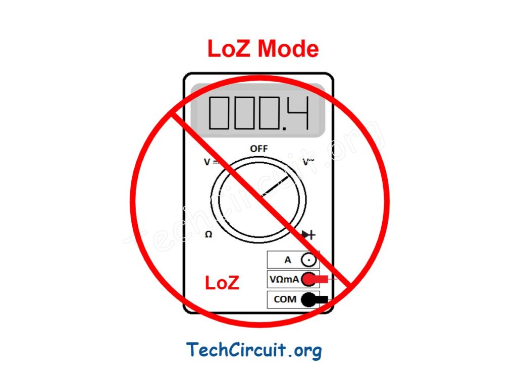
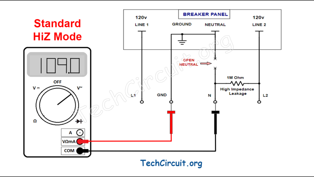
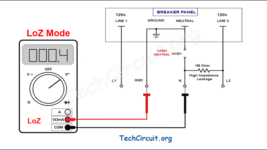
This voltage difference should be tested in HiZ mode, because LoZ mode pulls neutral and ground together – giving you a false reading. Below is the voltage difference between ground and neutral being tested in typical HiZ mode, and then with LoZ mode. Given some high impedance leakage current from L2, HiZ tell you that neutral and ground are disconnected by giving you a reading of over 100v. LoZ on the other hand, “pulls” the two together, with a reading of 0.4v, giving you a false impression that ground and neutral are at the same potential.
Example #2: Testing Voltages Around High Impedance AC Components
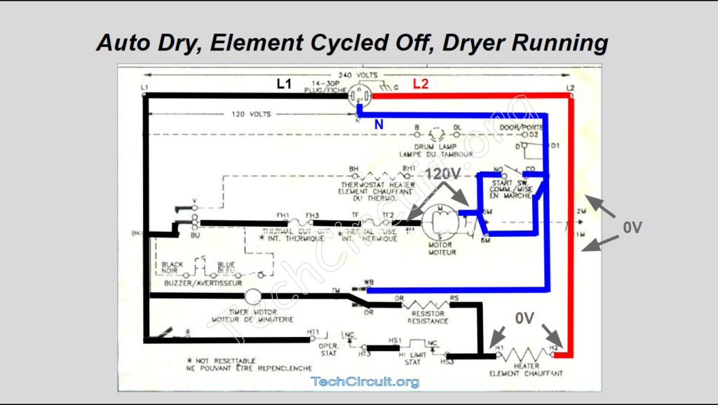
LoZ reduces the impedance at the point of measurement in a circuit. If the circuit depends on high impedance (or likewise high resistance) components, LoZ will change those values and thus change the way the circuit works. Take an electric dryer auto mode circuit for example. During auto-dry mode, the electric dryer’s cycling thermostat opens, allowing current (27mA) to flow through the heater, through a 4.5k ohm resistor, and the timer motor, which has an overall impedance of about 4.5k ohms. Thus, the 240v is split up among those two 4.5k ohm loads. The resistance of the element is so low, that the voltage drop across it is insignificant in this example (about 0.25v). So the timer motor and resistor each get about an equal share of the 240v (120v each).
However, if you were to connect one lead of your meter to L2 as a reference, to do some voltage testing in that circuit, and use LoZ mode, your 3k ohm meter’s low input impedance would be in parallel with the dryer’s 4.5k resistor, making it look like a 1.8k resistor. Using simple Ohm’s law, we can calculate the new current in that part of the circuit (38 mA) and realize that the motor now has V = I x R or 0.038A x 4500 = 171v across it instead of 120v. This not only gives you a false reading, but could burn out your timer motor during your test. In some other high impedance oriented circuits, this effect could be much worse. In the above example, by the way, the inductive reactance of the timer motor is omitted for simplicity and relevance.
Example #3: Testing Voltages on Control Boards and High Impedance DC Components
Some meters offer LoZ mode for DC voltage testing as well. However, unlike AC voltage testing, LoZ mode for DC voltage should be used with caution and sparingly. When working with low voltages and high impedance areas, such as probing around control boards, using LoZ mode can lead to undesirable outcomes.
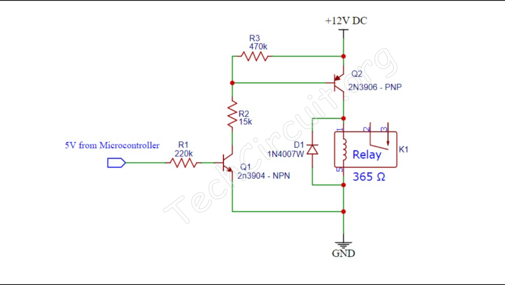
A specific example is when testing voltages around a relay circuit. In such cases, resistance values can exceed 100k ohms, particularly at the base of the relay control circuit. If you were to measure either side of that resistor with a LoZ meter in relation to ground, the high resistance values could potentially be reduced to less than 3k. This can result in significantly incorrect voltage readings and even change the operational state of the circuit. In some instances, it could even cause damage to the circuit.
Additionally, using LoZ mode for testing switching power supplies can have catastrophic effects. These power supplies rely on delicate balances of voltages and currents, which can be disrupted by the low impedance introduced by a LoZ meter, potentially leading to adverse consequences.
Example #4: Measuring Voltages Associated with Ground Fault Circuit Interrupters
This may not come up often. However, some Technicians tend to use ground as a reference when troubleshooting. Although it isn’t good practice, using ground in conjunction with LoZ may cause inadvertent tripping of GFCI protected voltage sources. In fact, when tying one lead to ground, by definition, you will trip a GFCI circuit with the low impedance introduced by LoZ when measuring protected voltages sources. It only takes 6mA to trip a GFCI. Testing a 120v circuit with respect to ground using a 3K ohm input LoZ meter, causes 120v / 3k = 40mA to flow to ground. This is well above the threshold, and will trip the circuit. It is important to understand this as GFCI protection becomes more prevalent.
Recommended LoZ Meter
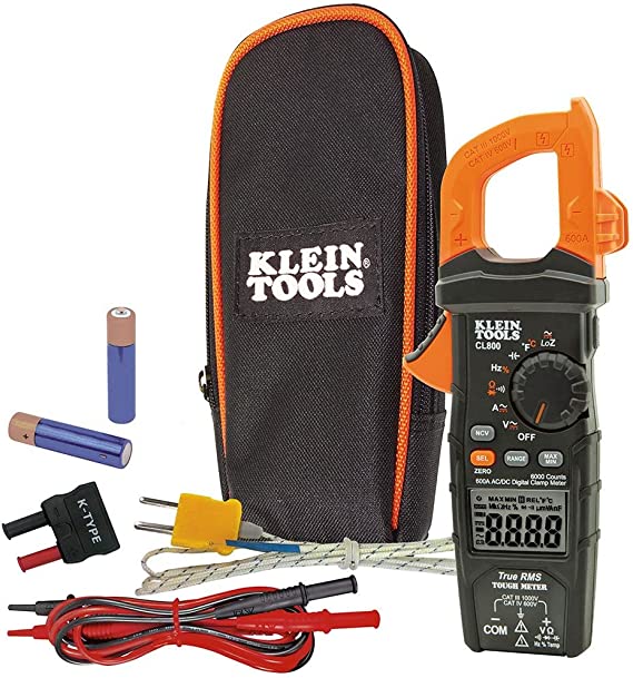
The Klein CL800 is an excellent all-around meter for field technicians. It offers comprehensive functionality, encompassing nearly every feature one would require in the field, including LoZ testing for both AC and DC voltages. Creating and writing articles like this one requires a significant amount of time and effort. I do receive a commission from any sales made through the provided link, and I genuinely appreciate your support.
CLICK HERE FOR RECOMMENDED LoZ METER
Test Your Knowledge!
What did you learn from this blog? Take the 12 question quiz and find out!
Understanding When Appropriate to use a LoZ Meter
Select the best answer for each question.
To donate to the Tech Circuit – CLICK HERE
For additional electrical and electronics learning material for field techs, visit our homepage at http://www.TechCircuit.org or our Facebook group at https://www.facebook.com/groups/746823709133603 or our YouTube Channel
at https://www.youtube.com/@TheTechCircuit
TC
We are a participant in the Amazon Services LLC Associates Program, an affiliate advertising program designed to provide a means for us to earn fees by linking to Amazon.com and affiliated sites.