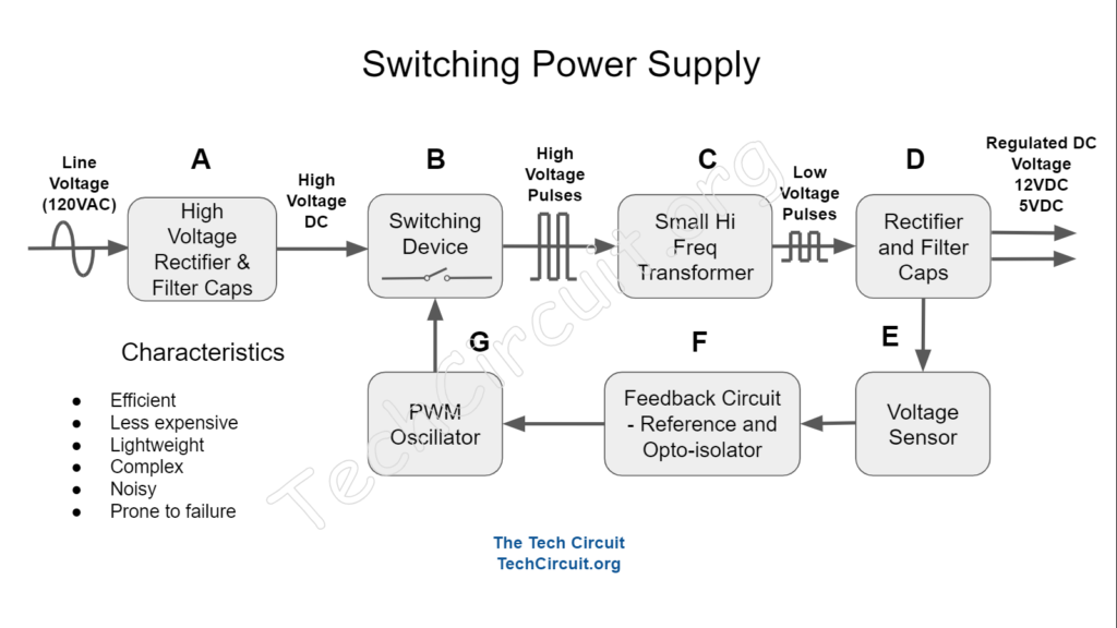
In this article, we’ll go into detail, how an SMPS or Switched Mode Power Supply works on a control board. We’ll talk about how the input filter works, initial rectification or conversion of AC into DC voltage, the switching circuit, high frequency transformer and galvanic isolation, feedback control circuit, and output rectification and filter. We’ll also discuss how some of these functional areas can fail, as well as what voltage references to use when troubleshooting.
What is an SMPS Power Supply?
As opposed to a simple linear power supply, which immediately steps the AC input voltage down to a low voltage, rectifies it, and filters it, SMPS supplies are more complicated. They operate at a much higher frequency and are thus able to use much smaller inductive and capacitive components in their design. This cuts component costs, and results in a more efficient voltage conversion.
SMPS Walkthrough on a Control Board
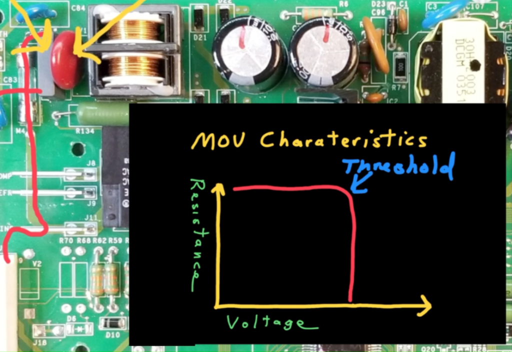
On the sample refrigerator control board, the line voltage comes in, passes through a fuse, and encounters a capacitor in parallel with L1 and Neutral. This capacitor resists rapid changes in voltage, which reduces high frequency noise. Also in parallel with L1 and Neutral, is an MOV, or metallic Oxide Varistor. This device has almost infinite resistance below a certain voltage, but approaches 0 ohms above a threshold, such as 400v. Such as in the case of a voltage surge caused by nearby lightning – resulting in the MOV taking out the fuse, and protecting the sensitive upstream circuitry.
Next is the EMI filter, which includes a common mode choke and additional capacitors. The EMI filter reduces high-frequency noise created by power supply, and reduces how much of that noise is fed back into the house supply.
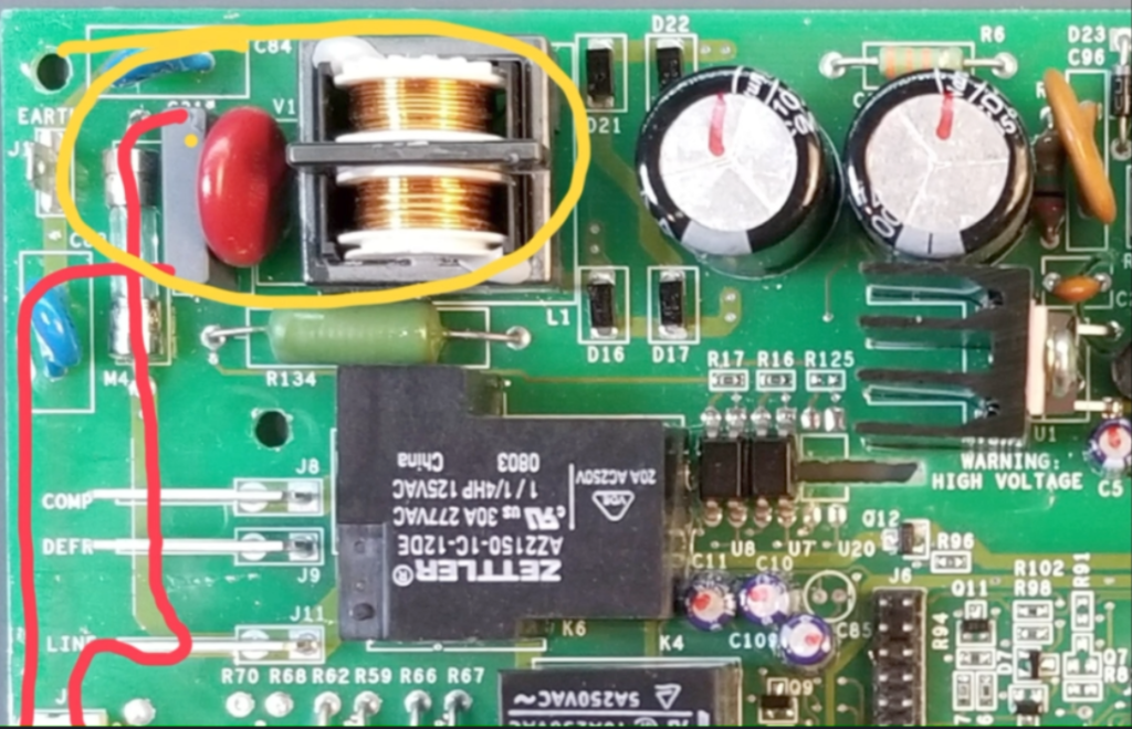
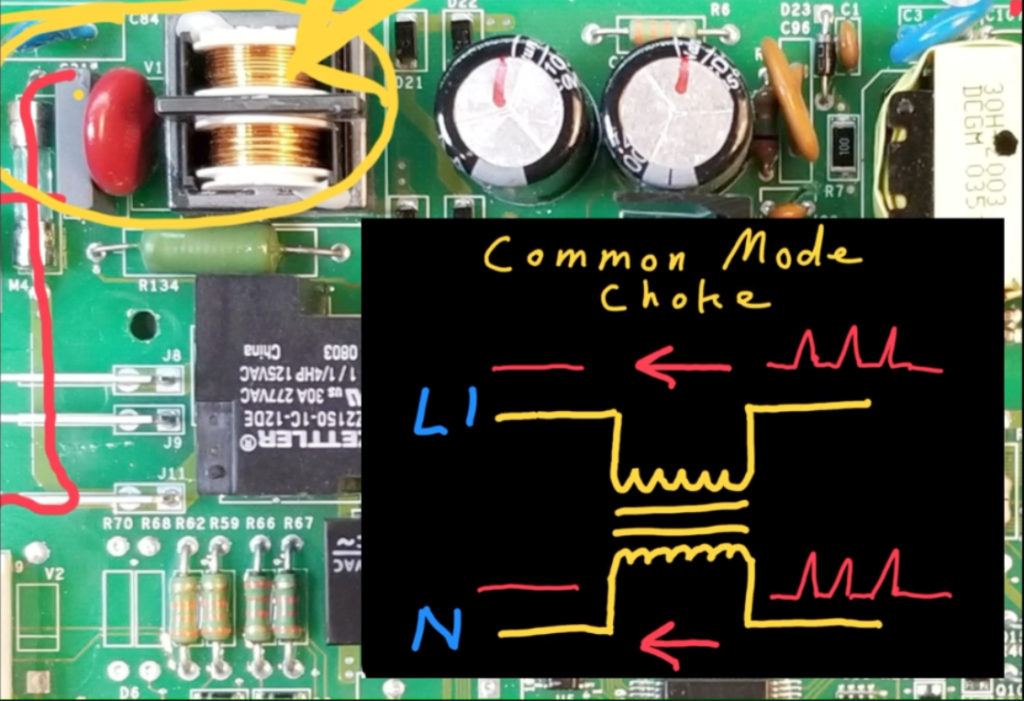
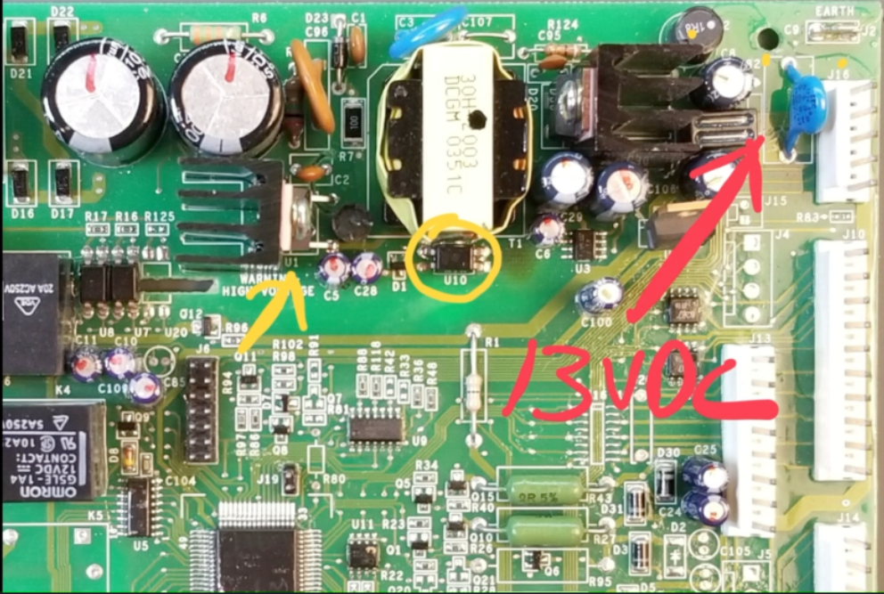
The common mode choke, designated by the yellow arrow, functions as a specialized dual inductor that resists high frequency current spikes originating from the power supply and is present on both lines (L1 and Neutral) simultaneously.
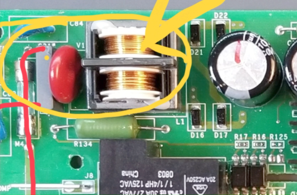
Its purpose is to prevent such noise, which occurs on both lines, from entering the house supply – as depicted in the image insert below.
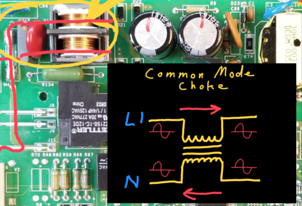
At the same time, it allows the low frequency cycling current of the 60 Hz sine wave to pass through without hindrance because normal current that flows in a circle is largely ignored by the behavior of this type of inductor – as shown.
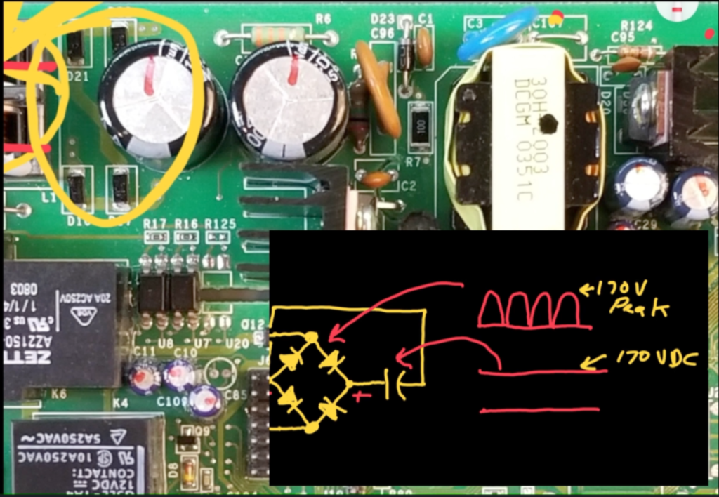
Next, the 120v AC line voltage is rectified by these four diodes, which are configured as a bridge rectifier.
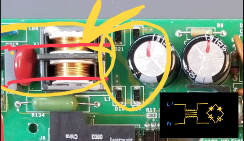
This rectifier transforms the AC waveform into a full wave rectified signal, which peaks at 170V (the peak value of the 120v RMS input voltage. This rectified signal charges the filter capacitors to approximately 170VDC as shown in the image below.
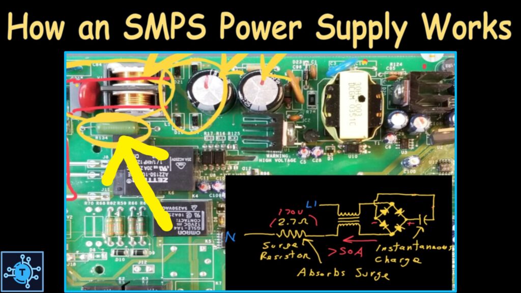
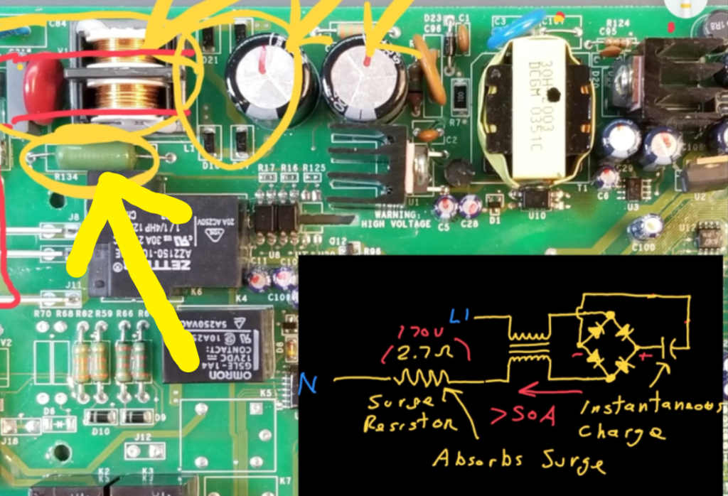
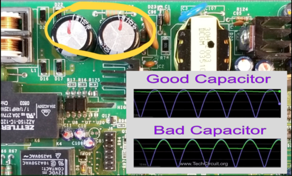
During the initial power-on the two large filter capacitors shown below, are prompted to charge instantaneously from sudden appearance of the rectified waveform. Since capacitors resist such instantaneous charging, a large amount of current flows into them. This current surge can be upwards of 50 amps. However, to protect the fuse from blowing due to this current spike, a low-value, high-wattage resistor is used. This resistor effectively absorbs the energy by inducing a temporary voltage drop (voltage = resistance x current) across it. As a result, the fuse is protected from blowing when you plug in the refrigerator and initially charge the capacitors.
Potential failures in this circuit block include diodes shorting out and blowing the fuse after a voltage surge that exceeds the reverse voltage rating of such diodes.
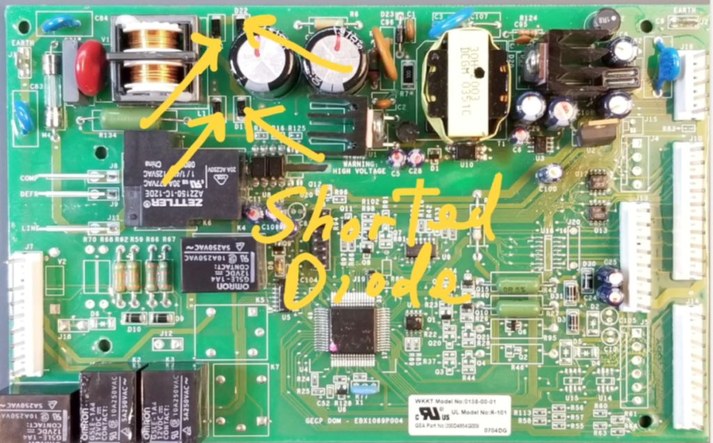
Additionally, the capacitors may develop high Equivalent Series Resistance (ESR), causing them to be ineffective in filtering out AC ripple in the rectified signal.
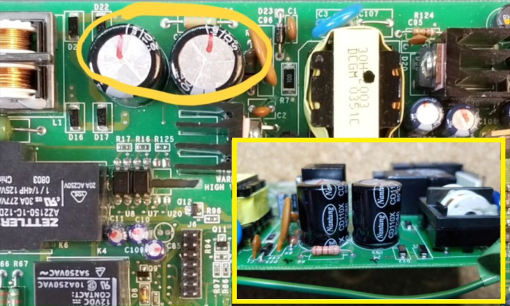
As a result, the power output from the supply could be reduced. Symptoms of such issues may include the power supply struggling to meet demands, a flashing display on the interface board, or a cyclical clunking noise.
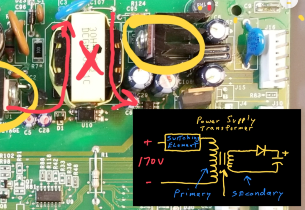
The below circled component acts as the power supply switching element, operating in series with the primary of the transformer at a high frequency. (It is specifically designed for SMPS or switch mode power supplies, and contains a high power transistor and supporting circuitry in the form of an IC with a heat sink). It is prone to failure, especially during voltage surges. Its purpose is to convert the DC stored in the capacitors into an AC voltage across the primary.
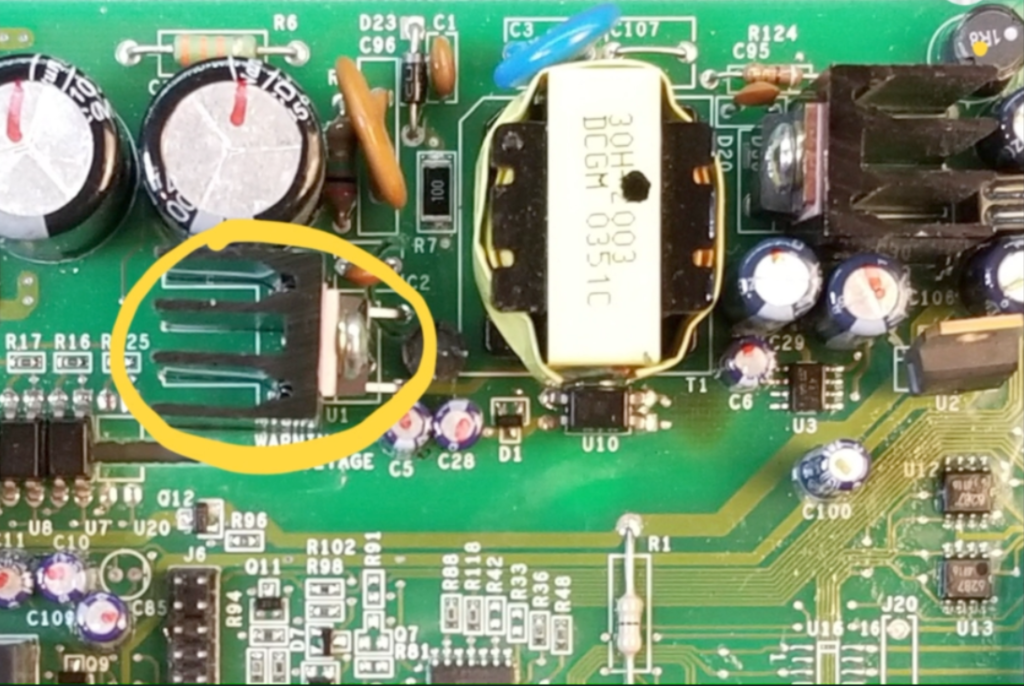
Consequently, an AC voltage appears across the secondary, which is much lower than that across the primary – to meet the system’s low voltage requirements.
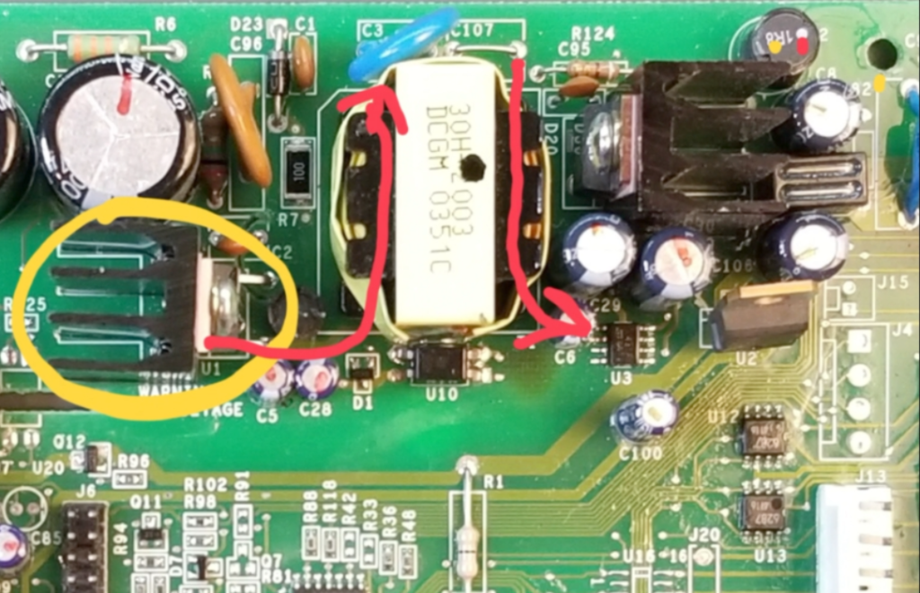
The secondary side of the transformer is isolated from the primary side because there is no direct connection between the two windings. This prevents a direct path for the current flow between the two transformer sides. Thus the output of the low voltage DC side of the board is does not seek earth ground or line voltage. This principle is known as galvanic isolation and helps protect the user of the appliance from electrical shock by not providing a voltage potential that seeks earth ground.
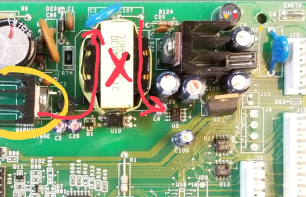
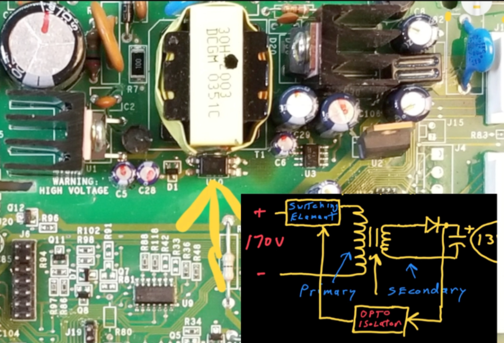
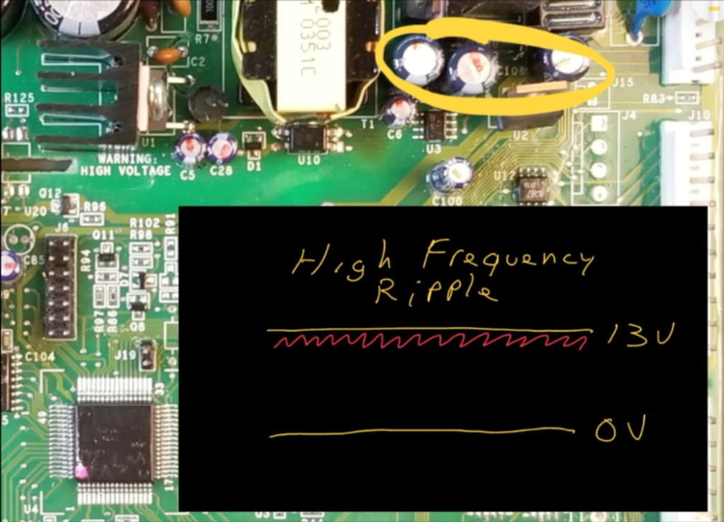
The AC voltage on the secondary is rectified by a single diode, resulting in a 13VDC stored across the capacitors.
SMPS supplies require feedback from the secondary to the primary side so that the output voltage can be regulated. Feedback is provided by an opto-isolator, which helps maintains the aforementioned galvanic isolation between the two sides using an LED and photosensor.
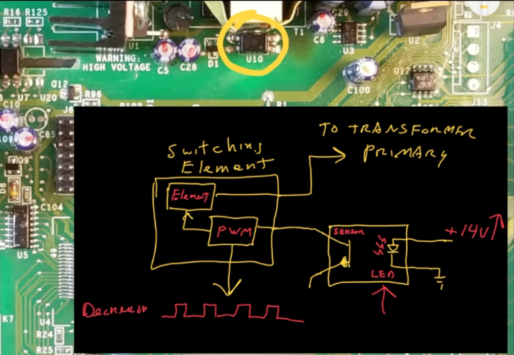
The presence of the internal LED light directly correlates with the voltage on the secondary. As the secondary’s voltage increases, the optocoupler’s LED turns on – telling the primary side that the secondary has reached its target voltage. Consequently, a PWM (pulse width modulation) signal decreases the duty cycle of the switching element so that less average voltage appears across the transformer’s primary and correspondingly, across its secondary.
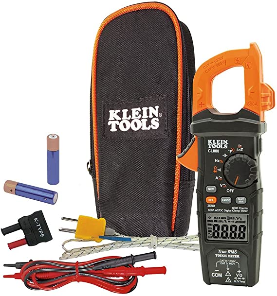
Recommended Multimeter for Appliance Repair
Conversely, when the LED turns off, a the PWM duty cycle increases , ultimately increasing the voltage induced on the secondary.
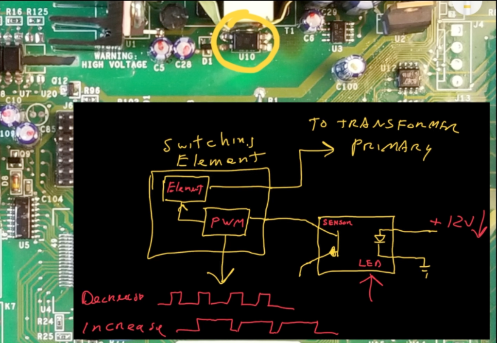
In this way, with the help of the optoisolator, the power supply maintains a regulated 13VDC output on the secondary.
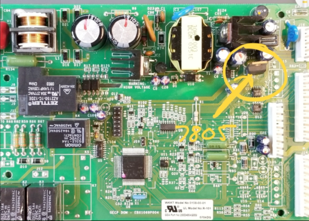
This common 7805 regulator (the 5 meaning 5v), further reduces the 13V to 5VDC, supplying power to the microcontroller and other 5V-dependent circuits. This power supply operates continuously to maintain constant power to the microcontroller.
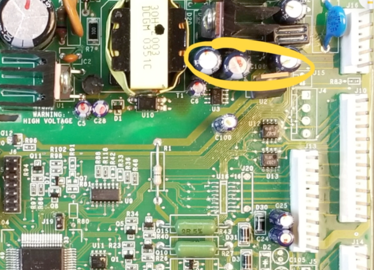
On the secondary side of the switched-mode power supply (SMPS), a common failure can occur with the filter capacitors. Due to the high operating frequency (>10kHz), these capacitors can be physically small yet still be required to handle substantial current. This leads to increased power dissipation and associated operating temperature, and evaporation of electrolyte – ultimately resulting in high Equivalent Series Resistance (ESR). Symptoms of this may resemble those of primary side capacitor failure, with the power supply struggling to meet demands.
Additionally, the resulting high-frequency ripple on the secondary can introduce noise in DC loads.
Voltage Measurement and Referencing Considerations
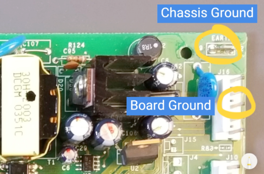
While the output of some control boards is directly tied to chassis ground, others are isolated from the chassis.
In cases like that, when troubleshooting or measuring voltages on the low voltage side, you would use board-ground, rather than chassis ground.
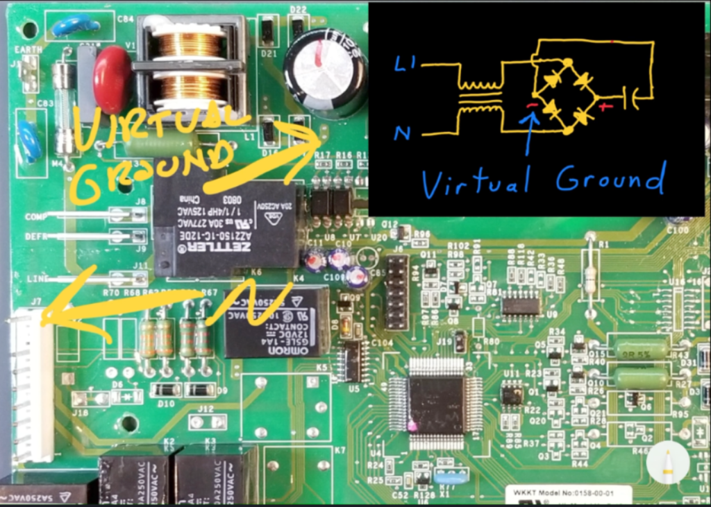
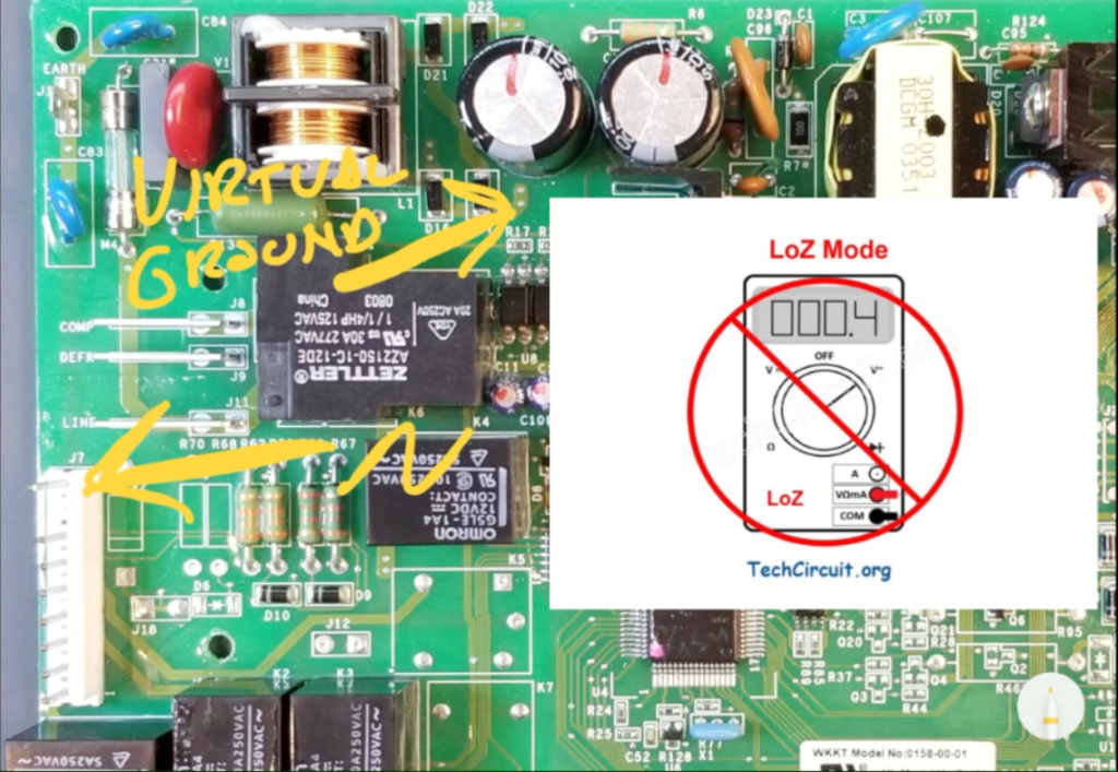
Also note that when measuring voltages on the primary side of the power supply, you will reference neutral until the voltage is rectified. Once rectified, a virtual ground is created by the bridge rectifier as shown below. That virtual ground would be the basis for DC voltage measurements on the primary side of the power supply.
Note that you will never want to use the LoZ mode of a voltmeter when measuring voltages in this section of the power supply primary- because the delicate balance of the SMPS power supply’s operation can be severely impacted by the relatively low impedance of the meter, and could very likely result in catastrophic failure of the supply and risk of injury to the Technician.
Test Your Knowledge of SMPS Power Supplies!
Take this quiz based on the content of this article, and see how high you can score! Answers to incorrectly answered questions are provided at the end of the quiz!
Understanding SMPS (Switch-Mode Power Supply)
Select the best answer for each question.
Summary
In this article we detailed the operation and theory behind the SMPS power supply, galvanic isolation, feedback, and failure points. We also discussed troubleshooting reference points and some dos and don’ts regarding live troubleshooting.
Disclaimer
This blog is intended for experienced or supervised technicians. Always take appropriate safety precautions when dealing with live circuits. For informational purposes only. Utilize the concepts in this blog at your own risk. The Tech Circuit or Steve Morrison assumes no responsibility or liability for any errors or emissions in the content of this blog. The information contained in this blog is provided on an as is basis with no guarantees of completeness, accuracy, usefulness, or timeliness. Never attempt to repair circuit boards in appliances or HVAC systems unless you are directly supervised by a licensed professional engineer and doing so under approved ISO and UL processes.
For a video version of this article, please see below or CLICK HERE.
I hope that you found this article educational and informative. Articles like this take a tremendous amount of time to compile. If you have found this helpful, please consider donating the the Tech Circuit:
To donate to the Tech Circuit – CLICK HERE
For additional electrical and electronics learning material for field techs, visit our homepage at http://www.TechCircuit.org
or our YouTube Channel at https://www.youtube.com/c/TheTechCircuit
or our Facebook group at
https://www.facebook.com/groups/746823709133603.
We are a participant in the Amazon Services LLC Associates Program, an affiliate advertising program designed to provide a means for us to earn fees by linking to Amazon.com and affiliated sites.