Introduction
In this blog, we will describe what diodes are, how they function, and how to test them. We will identify two of the most common types of diodes encountered by Technicians, and describe how to test them in circuit and out of circuit. Additionally, we will discuss the most common ways that diodes fail and how to identify such failures.
Important Note
Never attempt to repair circuit boards in appliances or HVAC systems unless you are directly supervised by a licensed professional engineer and doing so under approved ISO and UL processes.
Diode Theory
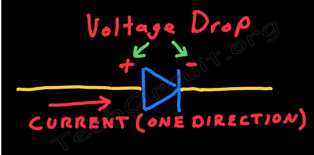
Diodes are semiconductor devices based on the P-N junction. A P-N junction in a diode is a fusion of differing semiconductor materials so as to pass current in only one direction. Thus a diode acts as kind of a one-way valve for electron flow. It has many uses including AC to DC rectification, logical functions, and dampening inductive spikes to name only a few. This one way passage of electron flow comes with a trade-off though. Diodes “consume” a little bit of the voltage in the circuit in which they are utilized. That is to say, they have a voltage drop when they are passing current. The state that they are in when they are passing current is known as the forward-biased state. Conversely, when a diode is reverse-biased, current is effectively blocked, and does not flow in the circuit. This blog shows you how to test diodes of different types with a multimeter, what some of the failure modes of diodes are and the associated multimeter readings. This blog will also touch on how special types of diodes can’t be readily tested with a multimeter, but can be with a little additional know-how.
Be sure to subscribe to our Youtube Channel!
For tons of videos on electrical and electronics diagnostics, practical electrical theory, and field-technician resources, click the picture below or this link here: https://www.youtube.com/@TheTechCircuit?sub_confirmation=1

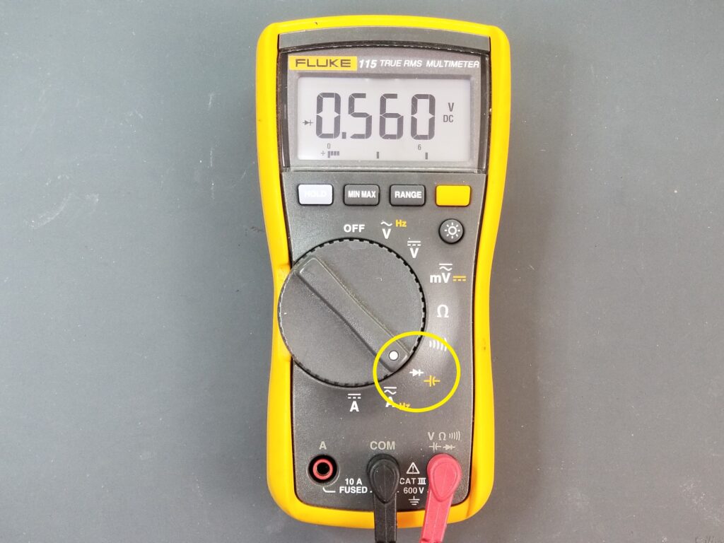
Multimeter Diode-check Function
If you try to measure a diode with the multimeter’s resistance function, you won’t be able to test it. The resistance function does not apply enough voltage across the diode to forward bias it. As mentioned, when diodes are “forward-biased”, they exhibit a voltage drop. Multimeters that have a “diode-check” function apply a (typical max 2v) bias voltage across the diode under test. This voltage varies depending on diode’s forward drop. So when a diode is forward biased, you’ll read an average 0.7v drop across it, for a standard silicon diode, which is the most common. Reversing the diode will yield an “OL” or overload on the meter’s display, indicating that the voltage drop is greater than the maximum 2v bias voltage, or “out of range”. This tells you that the diode is “reverse biased” and not allowing current to flow.
Testing a Standard Silicon Diode
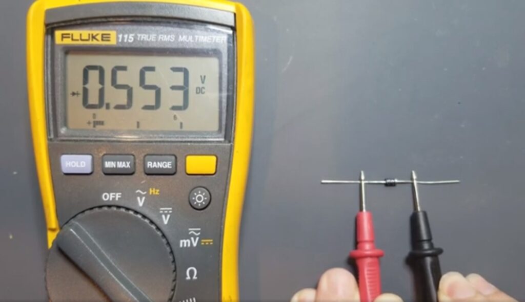
As mentioned, the standard silicon diode will have a voltage drop of around 0.7 volts. Diodes have an anode side and a cathode side. The cathode, or negative side, typically has a stripe on it. This is where you will place the black lead of the multimeter. The anode side is where you will place the red lead of the multimeter. This forward biases the diode. The diode below being read by the multimeter and is forward biased. It’s forward bias voltage, as you can see is 0.553 volts.
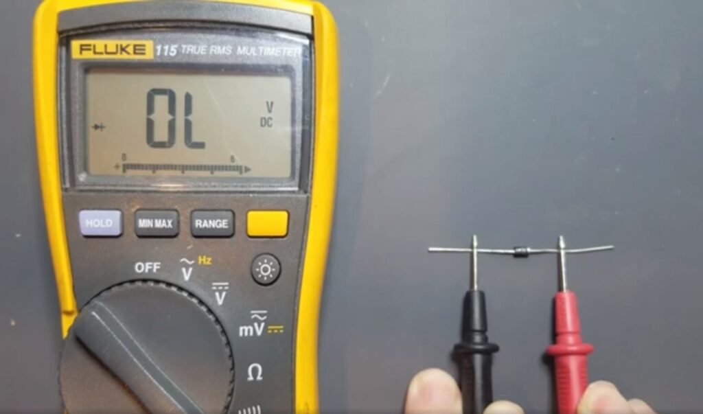
Reversing the diode shows an overload on the meter display as shown below. This is the reverse bias condition. Getting both these forward and reverse types of readings on a standard silicone diode indicates that the diode is in good functional condition.
Testing a Schottky Diode
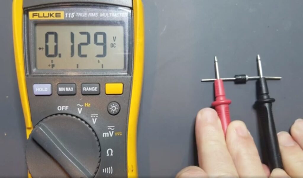
Schottky diodes are special types of diodes that are often used in switching power supplies. They have high switching speeds and typically lower voltage drops than standard silicon diodes. Schottky diodes can read a forward voltage drop as low as 0.1 volts. A typical forward voltage drop for a Schottky diode is around 0.3 volts. Having a lower forward voltage drop than a standard diode is very useful in electronics because you’re wasting less available voltage than you otherwise. This fact becomes relevant and power supplies and in other types of circuits where such voltage drops need to be accounted for. When testing diodes on control boards you will often find Schottky diodes within the SMPS (or switching power supplies) of those boards. The image shows a Schottky diode being tested with the diode check function and yielding a forward bias reading of 0.129v.
Purchase the Fluke 115, 116, or Klein CL800
Before we move on to in-circuit testing, there are several multimeters that I recommend for testing semiconductors. The Fluke 115, Fluke 116, and Klein CL800.
The Fluke 115 is a general purpose multimeter that also has capacitance, in-line current measurement, frequency, and other standard functions. CLICK HERE TO PURCHASE THE Fluke 115 Multimeter.
The Fluke 116 is more specific to the field service industry. It lacks in-line current measurement, but adds among other things, temperature measurement and the LoZ function, which are very useful for Appliance and HVAC Technicians. CLICK HERE TO PURCHASE THE 116 Multimeter.
The Klein CL800 is a comprehensive field service meter that has all of the popular functions for Appliance and HVAC Technicians. CLICK HERE TO PURCHASE THE Klein CL800.
Testing Diodes in-circuit
Testing diodes in circuit is done in the same manner I was out of circuit. Obviously you will want to remove power from the circuit board that you are testing. You will connect your leads to the diode in circuit as if you were testing it out of circuit. You should get the same type of readings while the diode is in circuit unless it is affected by other components on the board.
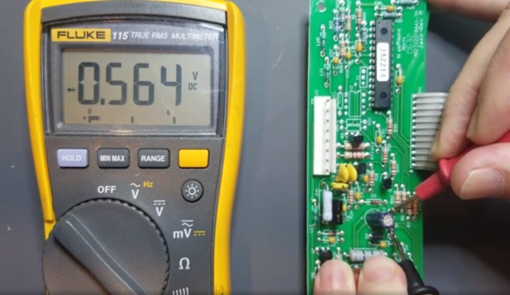
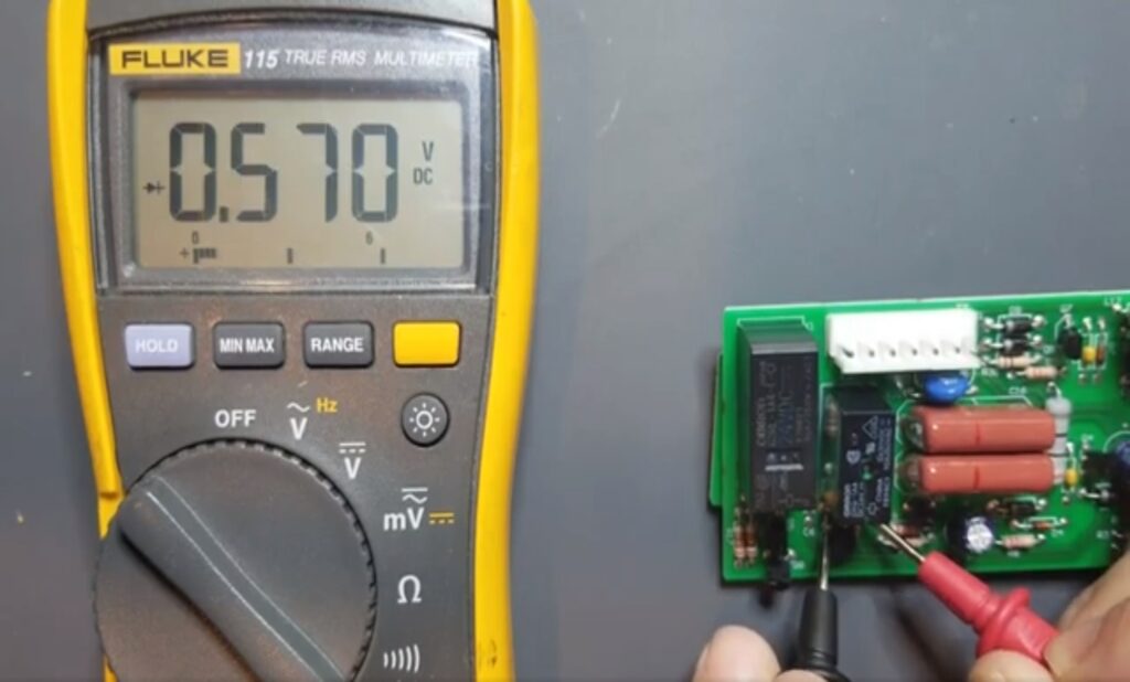
Shown below, a forward biased reading of a silicon diode while in-circuit and unaffected by surrounding components:
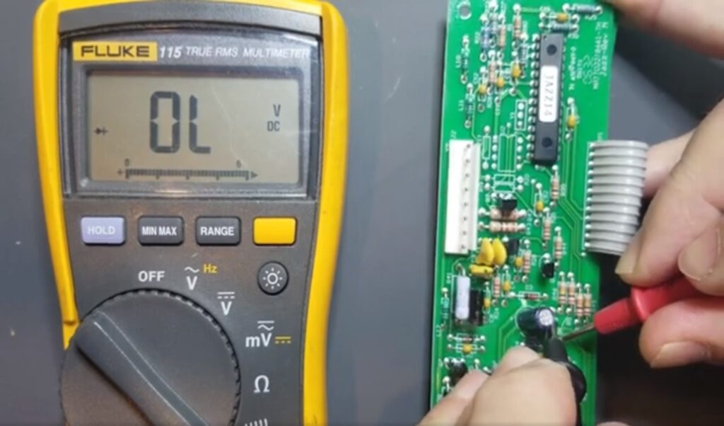
Shown below, a reverse biased reading of a silicon diode while in circuit, but largely unaffected by surrounding components.
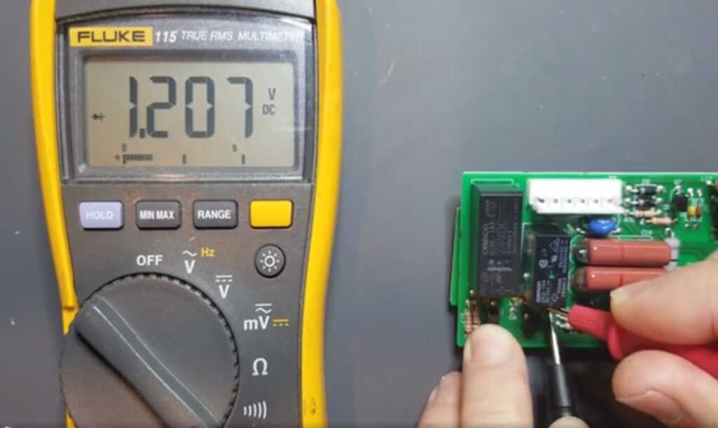
When a diode’s reading affected by surrounding components, a forward biased condition may read a lower forward bias voltage than you would if out of circuit. That’s OK. If you reversal leaves where you would normally read an overload for reverse bias condition, you may read something from the other components on the board. As long as the reverse bias reading is substantially higher than the forward bias reading, the diode is likely good. Sometimes diodes are connected across coils in order to dampen inductive spikes. In this case, depending on the relay coil’s resistance, you can get significantly lower readings than you would when you were testing the diode out of circuit. Sometimes you just have to remove a diode and test it out of circuit to be sure but it is reading properly.
In-circuit forward-bias testing of a flyback diode that is in parallel with a relay coil:
In-circuit reverse-bias testing of a flyback diode that is in parallel with a relay coil. This shows the atypical reverse-bias reading that results from the relay coil’s resistance.
Diode Failure Modes
As mentioned earlier. Attempting to measure a diode using the multimeters resistance function will normally not yield any useful results (unless it is leaky or shorted). This is because, again, the diode needs to be forward biased with a typically greater than 0.7 volt bias voltage before the diode starts conducting. However, if you are able to read less than 1000 ohms, for example across the diode using the resistance function the diode is likely bad. You will typically get close to the same reading both ways. In fact, silicone diodes when they go bad, they often short out. This makes the diode look very close to just a piece of wire. Typical resistance of a silicon diode that has failed and shorted out is going to be less than 10 ohms. You’ll read this resistance both ways. Leaky diodes will yield a reading both ways, but are just not shorted. Thus it is usually easy to identify a failed diode.
What might prompt you to try and use the resistance function in the first place to test a diode is getting a very low reading during diode check. That in itself is an indication that the diode is either bad or is picking up effects from other components on a circuit board if you’re testing a circuit. If testing the diode out of circuit and you’re still getting fairly low readings in both directions the diode has failed. One would then want to confirm this suspicion by switching to the resistance function of the meter and seeing whether the diode will give you a resistance reading in both directions.
Testing Other Diode Types
There are many types of diodes. In this article we just focused on two types of silicone diodes. Some older types of diodes use germanium as a semiconductor and typically have a much lower forward voltage drop. Zener diodes are another common type of diode that are intended to utilize their reverse voltage drop as a voltage reference. They are specifically designed to have a known reverse voltage drop which is commonly used for power supply regulation and other voltage reference applications. Testing Zener diodes is done differently. They cannot be tested with a multimeter’s standard diode check function. They can, however be tested in the manner as DESCRIBED IN THIS BLOG HERE. A Zener diode “test jig” is shown below. The fact is that all diodes have a reverse voltage drop. However, the diodes highlighted in this article – the standard silicone and Schottky diodes, have a very high reverse voltage drop that is designed to be much higher than what would occur in their target application. Thus the reverse voltage drop is irrelevant for most diodes given that it is not exceeded.
Video Version of this Article
Below is a video version of this article. You can also FIND IT BY CLICKING HERE.
Conclusion
In this blog, we learned what diodes are, how they work, and how to test them. We talked about two common types of silicone diodes that are frequently encountered by Technicians when diagnosing boards. We discussed how to test them in circuit and out as well as how to identify whether those diodes have likely failed. We also discussed other types of diodes, such as Zener diodes, that require additional testing considerations, and have linked to a blog that shows how to test them.
Disclaimer
This blog is intended for experienced or supervised technicians. Always take appropriate safety precautions when dealing with live circuits. For informational purposes only. Utilize the concepts in this blog at your own risk. The Tech Circuit or Steve Morrison assumes no responsibility or liability for any errors or emissions in the content of this blog. The information contained in this blog is provided on an as is basis with no guarantees of completeness, accuracy, usefulness, or timeliness. Never attempt to repair circuit boards in appliances or HVAC systems unless you are directly supervised by a licensed professional engineer and doing so under approved ISO and UL processes.
I hope that you found this article educational and informative. Articles like this take a tremendous amount of time to compile. If you have found this helpful, please consider donating the the Tech Circuit:
To donate to the Tech Circuit – CLICK HERE
For additional electrical and electronics learning material for field techs, visit our homepage at http://www.TechCircuit.org
or our YouTube Channel at https://www.youtube.com/c/TheTechCircuit
or our Facebook group at
https://www.facebook.com/groups/746823709133603.
We are a participant in the Amazon Services LLC Associates Program, an affiliate advertising program designed to provide a means for us to earn fees by linking to Amazon.com and affiliated sites.