Important Note
Never attempt to repair circuit boards in appliances or HVAC systems unless you are directly supervised by a licensed professional engineer and doing so under approved ISO and UL processes.
What Can Happen to a Relay Control Circuit if you Replace an RT334012 with an OZ-SS-112LM1
These results are based on a standard low-side NPN relay control circuit (the most common type). The components selected are such that the circuit is just sufficient to control the RT334012 relay. Most relay circuits should be designed with some overhead to handle more current. However, every design is different – and we must assume the control circuits are designed for a relay of the specified coil resistance/current.
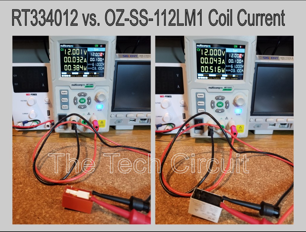
26% Decrease in Coil Resistance Caused a 35% Increase in Coil Current and thus Control Transistor Current
Resistance Decrease in %:
Original resistance = 365Ω, New resistance = 270Ω. % decrease = 100 x (Original – New)/Original = 100 x (365-270)/365) = 26%. CURRENT INCREASE IN %: Original current = 12v/365Ω = 32.8mA, New current = 12v/270Ω = 44.4mA. % increase in current = 100 x (New – Original)/Original = 100 x (44.4 – 32.8)/32.8 = 35%
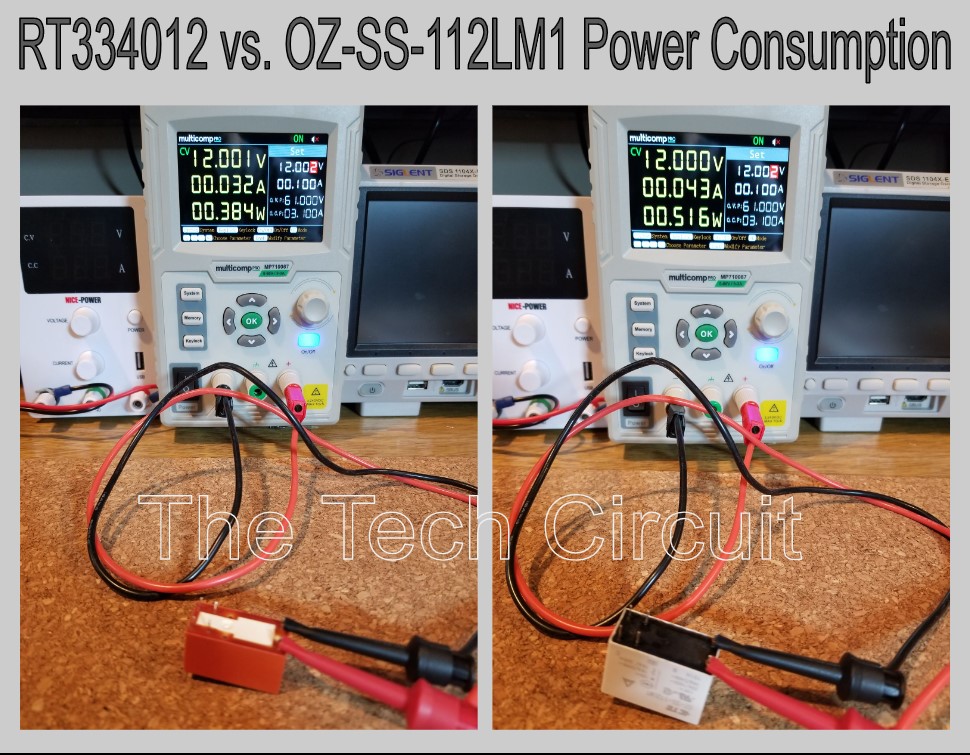
26% Decrease in Coil Resistance Causes the Relay to Consume 132% of the Original Power – This can Affect Power Supply Allocation – Particularly when Replacing Multiple Relays
Calculations:
0.516W – 0.384W = 0.132W increase. % increase = (100 x (1 + 0.132)) = 132%
Changing the Control Transistor Mode from a Switch to an Amplifier (Saturation to Active) – and Resulting Dissipation of More Power (Heat)
The image shows that the collector to emitter voltage across the control transistor increases to from 0.362 volts to 3.48 volts when the RT334102 is replaced by the OZ-SS-112LM1. A transistor configured as a switch should have a very low voltage across it when operating as a switch. The high current draw of the OZ-SS-112LM1 pushes the transistor from saturation into active mode – in which case it becomes an amplifier and experiences a 1000% power increase. The power dissipated by the transistor with the RT334102 is I X V = 0.031A x 0.362V = 11mW. The power dissipated across the same transistor with the OZ-SS112LM1 is 0.031A x 3.48V = 108mW (a 1000% increase in power or heat output).
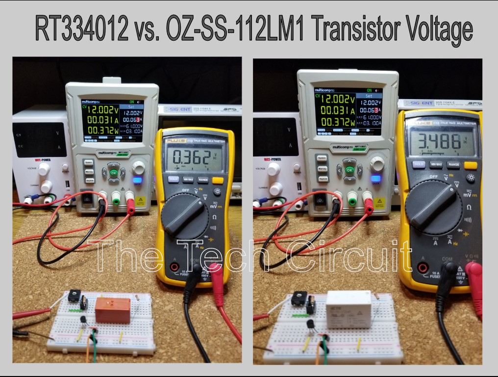
Less Voltage Available to the Relay Coil
In the above picture, the OZ-SS-112LM1 causes the control transistor to drop 3.48 volts of the available 12.00 volt supply. This leaves 8.2 volts available for the relay.
Disclaimer
This blog is intended for experienced or supervised technicians. Always take appropriate safety precautions when dealing with live circuits. For informational purposes only. Utilize the concepts in this blog at your own risk. The Tech Circuit or Steve Morrison assumes no responsibility or liability for any errors or emissions in the content of this blog. The information contained in this blog is provided on an as is basis with no guarantees of completeness, accuracy, usefulness, or timeliness. Never attempt to repair circuit boards in appliances or HVAC systems unless you are directly supervised by a licensed professional engineer and doing so under approved ISO and UL processes.