Important Note on Board Repair
Never attempt to repair circuit boards in appliances or HVAC systems unless you are directly supervised by a professional engineer and doing so under approved ISO and UL processes.
What is an Electrically Equivalent Replacement Relay?
Some Appliance and HVAC Technicians perform board-level repairs and often replace relays. Their replacement methodologies vary – ranging from only using exact replacements or electrical equivalents to electrically similar relays. The first two are suitable replacements, which don’t modify the board’s circuitry. The latter may include relays that meet most specifications except coil resistance – which is not an electrical equivalent. As a lifetime electronics hobbyist, having designed hundreds of circuits and repaired countless boards, I have always intuitively considered coil resistance when replacing relays – even back in the TV repair days. This article will explain the importance of coil resistance, how it affects the circuit board, and what could happen when not considered. As well, a relay substitution guide is provided for quick-reference.
Here are important relay parameters that determine both its electrical and electronic equivalency.
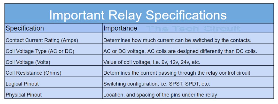
In lieu of an exact replacement, Technicians should use an electrical equivalent. By definition, an electrical equivalent relay will address all of the above specifications, including coil resistance – an approach followed by major board repair houses [6]. There are other specs such as “coil current”, “release times”, “must operate” and “must release” voltage – but are largely irrelevant to the Technician, except coil current – which is automatically addressed by selecting the proper voltage and coil resistance.
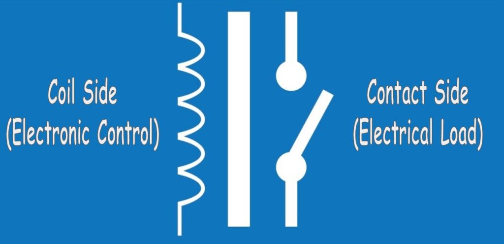
What is a Relay?
It is an electromechanical device that electrically isolates the control circuitry from the load. The load will be on the contact side, and the control circuitry on the coil side. A relay also serves as a bridge between Electricity (flow of electric power – contact side) and Electronics (flow of electrons and manipulation thereof – coil side).
Be sure to subscribe to our Youtube Channel!
For tons of videos on electrical and electronics diagnostics, practical electrical theory, and field-technician resources, click the picture below or this link here: https://www.youtube.com/@TheTechCircuit?sub_confirmation=1

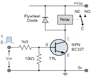
What is a Relay Control Circuit?
Most often, it is a transistor set up as a switch. It is turned on and off by a microcontroller. When it is on, it is like closing a switch and activating the relay. Most relay control circuits that Technicians encounter will be DC circuits. That’s why the relay coils are rated in DC voltage (i.e. 12VDC, 24VDC, etc.) Even though a relay coil is an inductor – it matters not to the relay circuit – other than having a diode that protects the transistor from a transient voltage spike when the relay is turned off. Since the relay coil’s resistance determines the current through the transistor, Engineers select the rest of the components (transistor and resistors) based on that coil resistance.
What Happens if you Replace a Relay with the Wrong Coil Resistance?
The circuit that controls the relay is designed around two primary things: Coil voltage and coil resistance. The second one “coil resistance”, which is listed on most datasheets as being within + or – 10% tolerance, determines the following:
- DC coil current
- What type of transistor is used to control it
- What value of resistors are used around the control transistor
- The value of the resistor between the microcontroller and the control transistor
Omitting coil resistance in the relay substitution process can result in the control circuitry being modified beyond its original design. Here’s why:
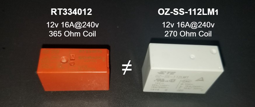
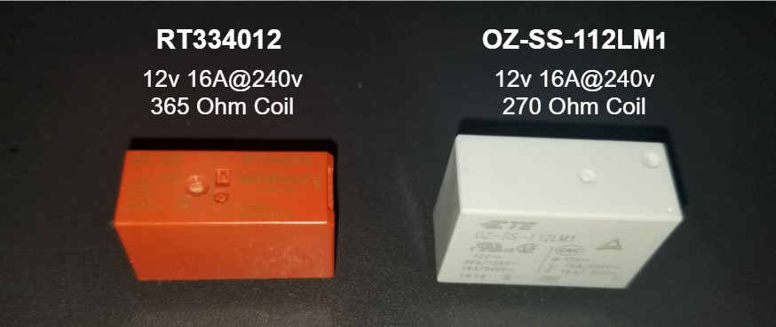
Let’s consider a case where the Technician replaces a 365 ohm RT334012 with a 270 ohm OZ-SS-112LM1 relay. They’re both 12v, 16A@240v SPST relays, with the same pinout. Some Technicians may consider the OZ-SS-112LM1 to be a drop-in replacement. The coil resistance of the OZ-SS-112LM1, however, is is 26% less than the RT334012. Percentage wise, this is significant. Remember, Engineers depend on a datasheet’s specified coil resistance and tolerance for their designs (again, usually – + or – 10%). Here are some things that can, but won’t necessarily happen to a relay circuit with such a reduction in coil resistance.
- Significant, (out of spec) increase in the control circuit current (26% decrease in resistance causes a 35% increase in current) [1]
- Invalidation of the designed component values (control transistor, peripheral resistors, microcontroller interface resistor)
- Changing the mode of the control transistor from a switch to an amplifier (saturation to active), and causing it to overheat. Overheated semiconductors tend to short out (become closed circuits), which can theoretically cause the relay to stay in the “on” state and behave like one with fused contacts. [2]
- Less voltage available to the relay coil [2]
- Overloading of the DC power supply allocation to the relays (when multiple relays are replaced and energized at once). Replacing two relays with a 26% decrease in resistance (like a bake and DLB) causes the relay circuit to use 170% of the design current and power from the DC supply. [1]
- Increased current draw from low resistance relays can cause degraded, high ESR caps in the power supply to manifest prematurely.
- Using a relay with an even lower coil resistance can exponentially amplify these effects.
Electrical Equivalents of Substituting an “out of spec” Relay
To put things in a different perspective – here are some exact proportional electrical equivalents of coil resistance difference and/or associated current increase by replacing a RT334012 with a 0Z-SS-112LM1:
- Substituting a 10 ohm, 5760 watt electric dryer element with one that has a resistance of 7.5 ohms that when installed, would release 7680 watts of heat (a 33% increase in both current and wattage). [3]
- Substituting a 3 amp oven ignitor with one that draws 4 amps. [4]
- Replacing a 365 ohm resistor with a 270 ohm resistor on a control board. [5]
- Proportionally, replacing a part that was specified to draw 34 amps, with one that draws 44 amps. [7]
Not withstanding any risk differences between replacing an out of spec relay and the above list – and even without the obvious risks in doing so, most Technicians would never knowingly do any of the above. Replacing a RT334012 relay with a 0Z-SS-112LM1, is the proportional electrical equivalent to all of the above – simply based on Ohm’s law.
Conclusion
Despite the potential problems caused by relays with out of spec coils, most relay circuits and power supplies should be designed to handle them. However, we can all agree that a lot of bad designs are out there. Further, I have been able to demonstrate most of the above potential problems on a breadboard (LAB RESULTS HERE).
Thus it is important to maintain the integrity of a circuity board by not modifying it beyond its original design. You reduce this risk by using exact replacement or “electrically equivalent” relays. Fortunately, that is easy – given the rules of thumb below. Two of the major control board remanufacturing companies we contacted meet (at minimum) all of the below criteria when replacing/substituting relays. [6]
- First choice – Replace with the exact relay
- Second choice – Replace with electrical equivalent which takes in to account
- Correct coil voltage type (AC or DC) (use exact)
- Contact current rating (use equal or greater than)
- Coil voltage (use exact)
- Coil resistance (within 10% or of datasheet spec)
- Logical pinout (SPST, SPDT, etc.) (use exact)
- Physical pinout (use exact)
Even though problems with out of tolerance relay replacements are unlikely, it is imperative that when working on systems as complex and exacting as circuit board electronics, Technicians be aware of how the repairs they make to circuits, effect those circuits. If Technicians are to maintain the integrity of a circuit board, all of the above specifications should be addressed. Not doing so could mean they are installing a part that is outside of the original design tolerance (or a non-electrical equivalent), which is no different than soldering in a very different value resistor, which is by definition, electrically modifying the circuit.
Disclaimer
This blog is intended for experienced or supervised technicians. Always take appropriate safety precautions when dealing with live circuits. For informational purposes only. Utilize the concepts in this blog at your own risk. The Tech Circuit or Steve Morrison assumes no responsibility or liability for any errors or emissions in the content of this blog. The information contained in this blog is provided on an as is basis with no guarantees of completeness, accuracy, usefulness, or timeliness. Never attempt to repair circuit boards in appliances or HVAC systems unless you are directly supervised by a licensed professional engineer and doing so under approved ISO and UL processes.
Citations/References
Included in the references below is a link to (LAB RESULTS HERE) that show some of the ways that replacing a relay with a 25% decrease in coil resistance can detrimentally affect a relay control circuit.
- [1] RESISTANCE DECREASE IN %: Original resistance = 365Ω, New resistance = 270Ω. % decrease = 100 x (Original – New)/Original = 100 x (365-270)/365) = 26%. CURRENT INCREASE IN %: Original current = 12v/365Ω = 32.8mA, New current = 12v/270Ω = 44.4mA. % increase in current = 100 x (New – Original)/Original = 100 x (44.4 – 32.8)/32.8 = 35% (LAB RESULTS HERE)
- [2] Increasing a transistor’s collector current beyond its design can push it from saturation (switch mode) to active (amplifier mode) (LAB RESULTS HERE)
- [3] RESISTANCE DECREASE IN %: Original resistance = 10Ω, New resistance = 7.5Ω. % decrease = 100 x (Original – New)/Original = 100 x (10-7.5)/10) = 25%. CURRENT INCREASE IN %: Original current = 240v/10Ω = 24A, New current = 240v/7.5Ω = 32A. % increase in current = 100 x (New – Original)/Original = 100 x (32 – 24)/24 = 33%. Power increases proportionally to current for a fixed voltage. Thus power increase is also 33%.
- [4] Ignitor Example: Current increase (%) = 100 x ((4A – 3A)/3A) = 100 (1/3) = 33%
- [5] Replacing a 365 ohm resistor with a 270 ohm resistor in a 12v circuit means that the increase in current is (new current – old current)/old current = ( (12/270) – (12/365) ) / (12/365) ) = 0.35 x 100% = 35%
- [6] Phone interviews conducted on 7/27/2022 with two major board houses indicated that one explicitly takes all of a relay’s specifications into account, including coil resistance. Any substitutions or upgrades that are not electrical equivalents are done per the board manufacture’s specifications. The second major board house stated that “all relay specifications are matched, unless otherwise approved by the board manufacturer”.
- [7] Replacing a part that draws 34mA with one that draws 44mA is the proportionally same as replacing a part that draws 34 amps, with one that draws 44 amps. Here are the proportions of those respective scenarios: Case 1) 0.044A/0.034A = 1.3, In % this is 1.3×100 = 130% more current. Case 2) 44A/34A = 1.3. In % this is 1.3 x 100 = 130%. The two cases are proportionally the same.
To DONATE to the Tech Circuit – CLICK HERE
Alphabetical Links to all Tech Circuit Articles and Blogs – CLICK HERE
Links to all Tech Circuit Cheat Sheets/Field References for Appliance/HVAC Techs – CLICK HERE
For additional electrical and electronics learning material for field techs, visit our homepage at http://www.TechCircuit.org or our Facebook group at https://www.facebook.com/groups/746823709133603, or our YouTube Channel
at https://www.youtube.com/c/TheTechCircuit