Build a Microwave Diode Tester

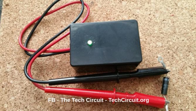
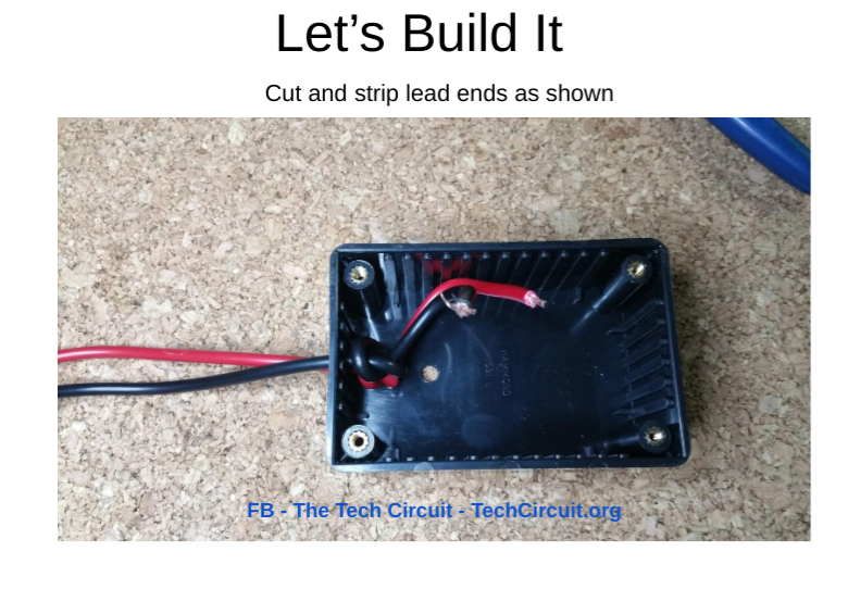
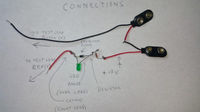
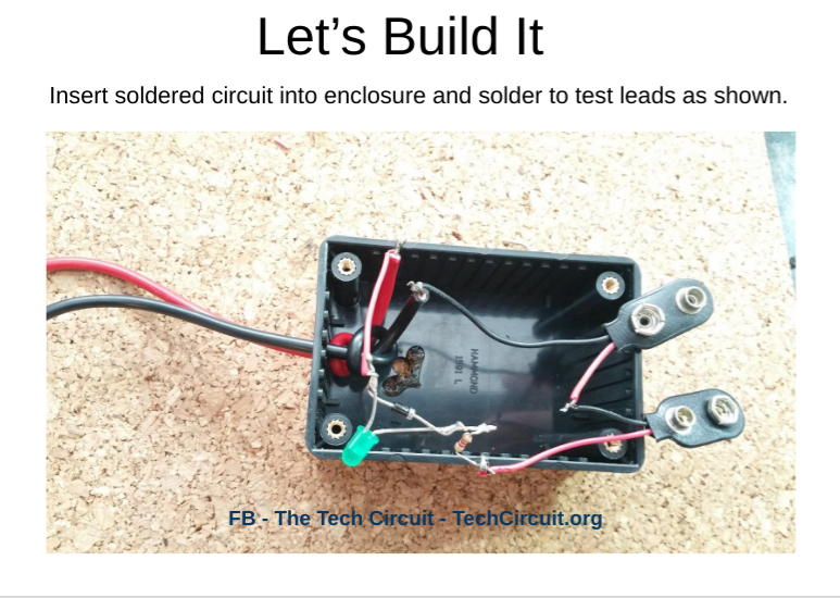
Build a microwave diode tester that shows a green light for forward bias. It uses 18V to ensure enough voltage to forward bias the diode. This tester can also be used for biasing zener diodes and semiconductor junctions in general. In this article, a detailed description and instructions are provided, along with a parts list, for the reader to build the tester. The circuit and components are simple and cheap. It should cost less than $20. The final product is shown below:

Figure 1 – Microwave Diode Tester
Figure 2 – Microwave Tester Schematic Diagram
Figure 3 – Overview of Different Diode Types
Figure 4 – Mark Location for Lead Holes.
Figure 5 – Drill Lead Holes
Figure 6 – Final Drilled Lead Holes
Figure 7 – Cut Test Leads to Desired Length
Figure 8 – Pull and Knot Leads for Strain Relief
Figure 9 – Pull Leads Back so Knot is Against Inside of Case
Figure 10 – Cut and Strip Internal Lead Ends
Figure 11 – Measure for LED Hole
Figure 12 – Drill LED Hole
Figure 13 – Component Connections
Figure 14 – Insert Components into Enclosure
Figure 15 – Use Heat Shrink Tubing to Insulate Connections
Figure 16 – Epoxy Lead Wires and Components in Place
Figure 17 – Fully Constructed Tester

We are a participant in the Amazon Services LLC Associates Program, an affiliate advertising program designed to provide a means for us to earn fees by linking to Amazon.com and affiliated sites.

Leave a Reply