Introduction:
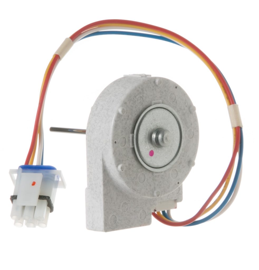
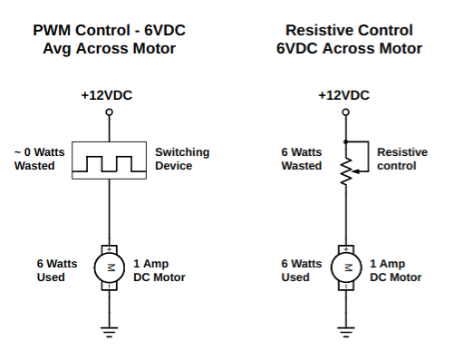
PWM, or Pulse Width Modulation, aside from being the preferred method for controlling LED lighting, is a common way to control DC motors as compared to simple varied DC voltage. This is because with PWM, the motor still receives full power in the form of pulses, while at the same time, varied average power for speed control. It can do this because when pulses are high, no matter how brief, full operating voltage is applied to the motor. Only the duration of this pulse within each square-wave time period is varied. This results in a motor that can turn slowly, but have much more torque than simply varying the voltage. Also, PWM switching, relative to some other methods, reduces waste power dissipation among switching components such as transistors because they are used in either ¨on¨ or ¨off¨ mode. In fact, PWM, relative to resistive or varied resistance control, dissipates almost no waste power. Field technicians may notice that PWM is commonly used for controlling variable speed DC fan motors in appliances such as refrigerators.
PWM Waveform
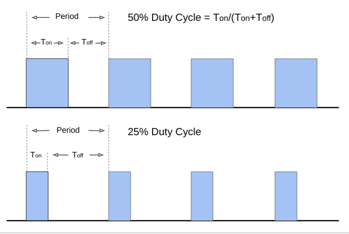
PWM varies the ¨duty cycle¨ of the applied square wave. For example, a square wave with a period of 0.01 seconds with a 50% duty cycle has symmetrical on and off times at a frequency of 100 Hz. In other words, 50% of the time it is on and 50% of the time it is off. Thus a 12VDC motor driven by a 12V, 50% duty cycle PWM square wave receives an average voltage of 6V, yet have full power for the moments the pulse is high. So a square wave with a 25% duty cycle would yield an average voltage of 3 volts.
To calculate the duty cycle, divide the (On) time by the (On+Off) time. Then multiply by 100 and you will have your duty cycle in percent. A duty cycle of 50% translates to equal on and off times. The diagram below graphically illustrates a Pulse Width Modulated DC voltage.
Advantages of PWM
Two major advantages of using PWM are:
Power delivery to the load – A 12 volt motor controlled by a 50% duty cycled PWM voltage gets the full 12V 50% of the time – providing for full motor torque, while the average voltage over time is only 6 volts. Thus less average power is being used. The result is a slower turning motor with high torque.
For LED control, when the PWM pulse state is high, the LED gets a full and consistent current flow (through limiting resistors) and is at full brightness at a predictable wavelength (color).
Efficient control by driver components – Driver transistors or devices can be used in ¨full on¨ or ¨full off¨ state, which means they have no appreciable voltage drop across them when supplying current. So power dissipation and resulting heat is very low – meaning that relatively smaller and cheaper switching components can used and with less or no heat sinking.
Simple PWM Driver Circuit
PWM can be generated in a number of ways. It is commonly found as a native capability among many microcontrollers. It can also be software generated within them. Dedicated devices that generate PWM are also available. For this demonstration, a readily available 555 timer IC is used. In this circuit, the PWM derived from the 555 timer is used to drive a high-side PNP driver transistor for delivering varied pulse widths to a DC motor. This circuit is shown below.

PWM Demo Circuit
Below the simple 555 timer based PWM circuit is used to control an appliance DC fan motor. The average voltage is varied by varying the applied voltage´s pulse width. On the screen, is shown the duty cycle % and associated average voltage to the load. Note that at the lowest speed, the motor has decent torque and very little tendency to stall out – since even at low speed, it is still receiving full power pulses – however brief.
We are a participant in the Amazon Services LLC Associates Program, an affiliate advertising program designed to provide a means for us to earn fees by linking to Amazon.com and affiliated sites.