Intro – What is a Relay Driver or Relay Control Circuit?
A relay driver circuit acts as a buffer between the control board´s intelligence and the relatively high current drawn from the relay coil. A microcontroller typically will output a high or low logic level (3.3 or 5v for a high, and 0 volts for a low) and is used to switch on a driver transistor or integrated circuit. For the example circuit shown below, an ¨active high¨ output is used. The microcontroller isn´t connected directly to the relay for several reasons. For one, it can´t typically supply enough current from its ports to energize the relay. Secondly, the relay coil creates voltage spikes that can damage the sensitive microcontroller´s ports. In the shown circuit, the microcontroller only needs to supply 4.3 mA from its output port to drive a 100mA relay coil. A pretty good deal for the microcontroller.
How a Relay Driver Circuit Works
The bipolar transistor based driver circuitry makes use of the transistor´s cutoff and saturation mode to control the relay. In other words, the transistor is used as a ¨switch¨. This is accomplished by carefully selecting resistor values that, in conjunction with the transistor´s gain, drive it far beyond what is necessary to fully conduct. Knowing the relay´s coil resistance and expected current flow within the circuit is key to those resistor selections. Thus the transistor is either switched on or off and dissipates almost no power.
Be sure to subscribe to our Youtube Channel!
For tons of videos on electrical and electronics diagnostics, practical electrical theory, and field-technician resources, click the picture below or this link here: https://www.youtube.com/@TheTechCircuit?sub_confirmation=1

Relay Driver Circuit – Step by Step
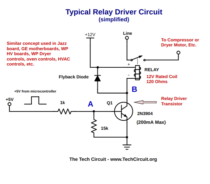
When the user enables the bake function on their oven, for example, the microcontroller outputs +5V DC from one of its ports. This, through a 1k current limiting resistor, puts the driver transistor Q1 into saturation from a cutoff state. This means that it has been ¨switched¨ on. Once this occurs, the current flows through the relay coil via Q1´s collector and energizes it – closing the normally open relay contacts. The diode in parallel with the relay coil clamps the high voltages spikes that occur when the relay coil is de-energized. This is needed to keep the spikes from damaging Q1 and possibly the microcontroller port driving Q1. The circuit depicted in the schematic is tested and functional. However, it is stripped down in order to show the key elements. Many variations of the shown circuit are used on control boards. Some have multiple stages, different driver devices such as ICs, and different methods for controlling those devices.
This video breaks out a simplified transistor-based relay driver circuit.
Don’t forget:
“Diverting 10 min/day of social media time towards learning something new, is 5 hours of newfound monthly knowledge.” – SM
To DONATE to the Tech Circuit – CLICK HERE
Alphabetical Links to all Tech Circuit Articles and Blogs – CLICK HERE
Links to all Tech Circuit Cheat Sheets/Field References for Appliance/HVAC Techs – CLICK HERE
For additional electrical and electronics learning material for field techs, visit our homepage at http://www.TechCircuit.org or our Facebook group at https://www.facebook.com/groups/746823709133603.
We are a participant in the Amazon Services LLC Associates Program, an affiliate advertising program designed to provide a means for us to earn fees by linking to Amazon.com and affiliated sites.