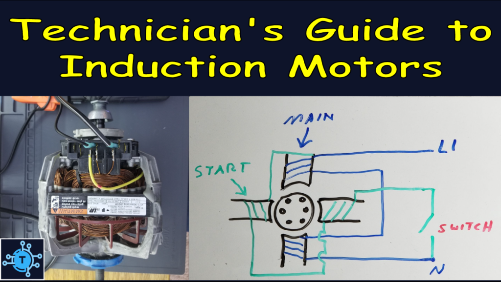
This article aims to explain the theoretical workings of single-phase induction motors in a way that individuals without an engineering background can understand. By the end of this article, readers should be able to describe the driving force behind the armature’s motion, how rotation is maintained, the reasons for needing start mechanisms, and the operational principles and differences among various types of single-phase motors.
Inducing a Magnetic Field in the Armature
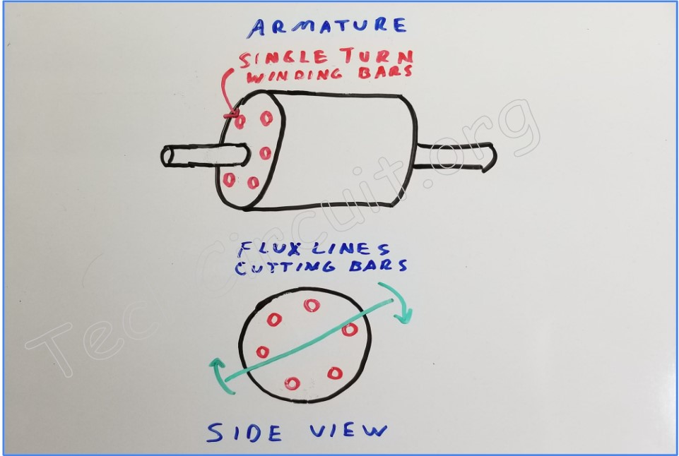
Induction motors (as the name implies) use the process of electromagnetic induction (inducing a voltage in a conductor by moving a magnetic field through it), which ultimately results in movement of the armature. There aren’t any permanent magnets. The armature simply consists of conductive bars, the ends of which are electrically connected. Each bar comprises a single-turn winding of what is essentially the secondary of a transformer. When the magnetic field (flux lines) of the stator passes over the bar, the EMF (electromotive force or voltage) that is induced in it causes a heavy current to flow through it. This current, in turn, causes the armature bar to develop its own magnetic field which follows the stator’s moving field.
Induction Motor “Slip”
Of course, in order to induce a magnetic field in the armature, the stator’s magnetic field must be moving relative to the armature. But how can this happen if the armature is moving and following the stator? The answer is that the armature does not follow the stator at its full RPM. The armature must be turning slower than the stator for there to be a relative speed difference between them. That relative speed is what induces the magnetic field in the armature and is known as “slip”. In fact, when putting the induction motor under load, the relative speed increases, the current through the armature windings increases, and the motor has more power to handle the increased load. An example of induction motor slip is that of a dryer motor, which has a rated RPM of 1725, but oscillates at 1800 RPM based on line frequency and the fact that it has 2 poles (divides the frequency by two).
How Induction Motors Start
The Problem with Single Phase Current
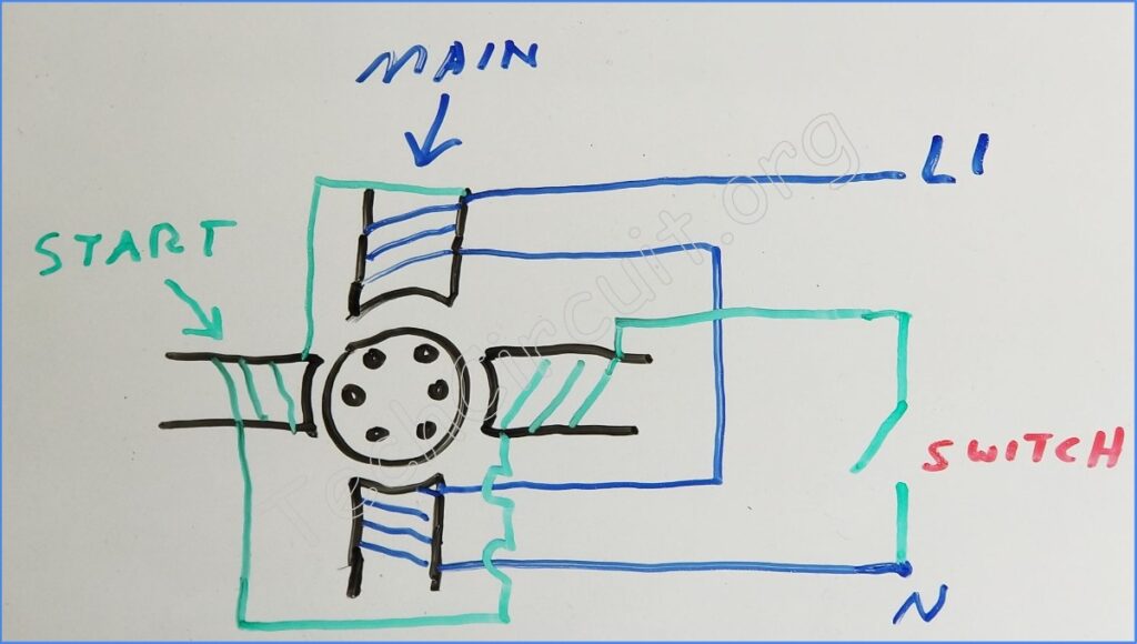
Single phase induction motors have an inherent problem though. A unity phase signal is not conductive to rotation. It only causes oscillation (back and forth movement between 2 poles directly across from each other – or 180 degrees apart). This in itself would only make the armature meander without any purpose. Somehow, a rotation needs to be derived from this single phase supply. A second (auxiliary) winding that is physically placed 90 degrees offset from the main winding allows for the possibility of a rotating, rather than oscillating magnetic field. However, if the auxiliary winding was energized with the same current as the main winding, it still wouldn’t facilitate rotation.
Splitting the Single Phase
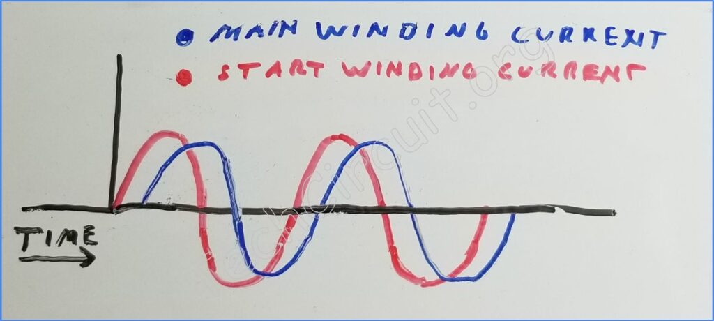
Fortunately there is a way to obtain multi-phase current from just a single phase. All motor windings have inductance. Inductors resist changes in current. Thus current change through inductors occurs at a later time than does the voltage. This means that the current lags behind the voltage in terms of time – also known as a phase shift. This fact can be exploited so that the current through the auxiliary winding can occur at a different time than of the main winding – resulting in a rotating magnetic field through the stator that provides directional guidance for the armature. There are a number of ways to accomplish this.
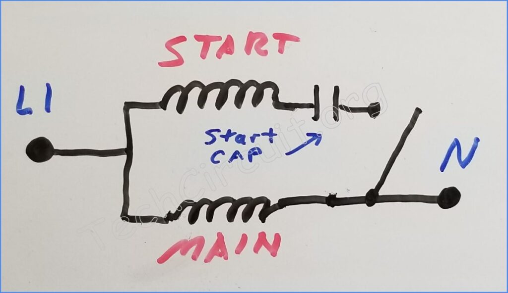
Capacitor Start Motors
Capacitors resist changes in voltage across them. This is the inverse of what inductors do. Thus, the change in voltage across a capacitor occurs later than the change in current – causing the voltage to lag behind the current. This makes capacitors ideal for shifting the auxiliary winding current away from that of the main winding. In fact, a start capacitor motor is able to obtain a large phase shift between the two windings, which gives the motor a relatively large starting torque. This is the main advantage of capacitor start motors, which are used in applications that require such large starting torque (washing machines, etc). Once the motor is running at a specific RPM, a centrifugal switch opens and the start winding is removed from the circuit. The oscillation between the 180 degree offset main winding poles is then enough to well maintain the armature’s rotation.
Split Phase Motors
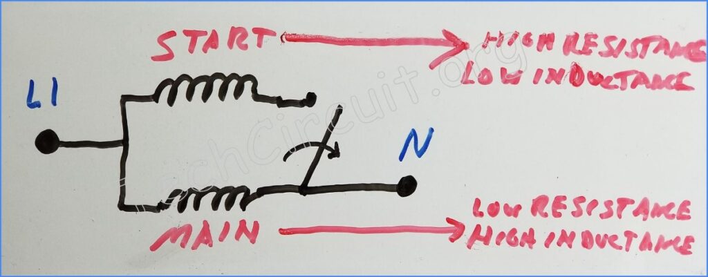
Split phase motors use a really neat trick to accomplish a phase shift between the start and auxiliary winding. They use no start capacitor. The main winding is wound in such a way that it has high inductance, but low resistance. Conversely, the auxiliary winding is wound so that it has relatively low inductance and high resistance. This relative difference in inductance means that the current through the main winding (by virtue of its higher inductive reactance) lags behind that of the less inductive start winding. This phase difference between the main and start winding’s current causes rotation. Like the capacitor start motor, the start (auxilliary) winding is removed from the circuit via a centrifugal switch – and the main winding’s oscillation is enough to sustain rotation at the motor’s nominal load and RPM.
Permanent Split Capacitor Motors
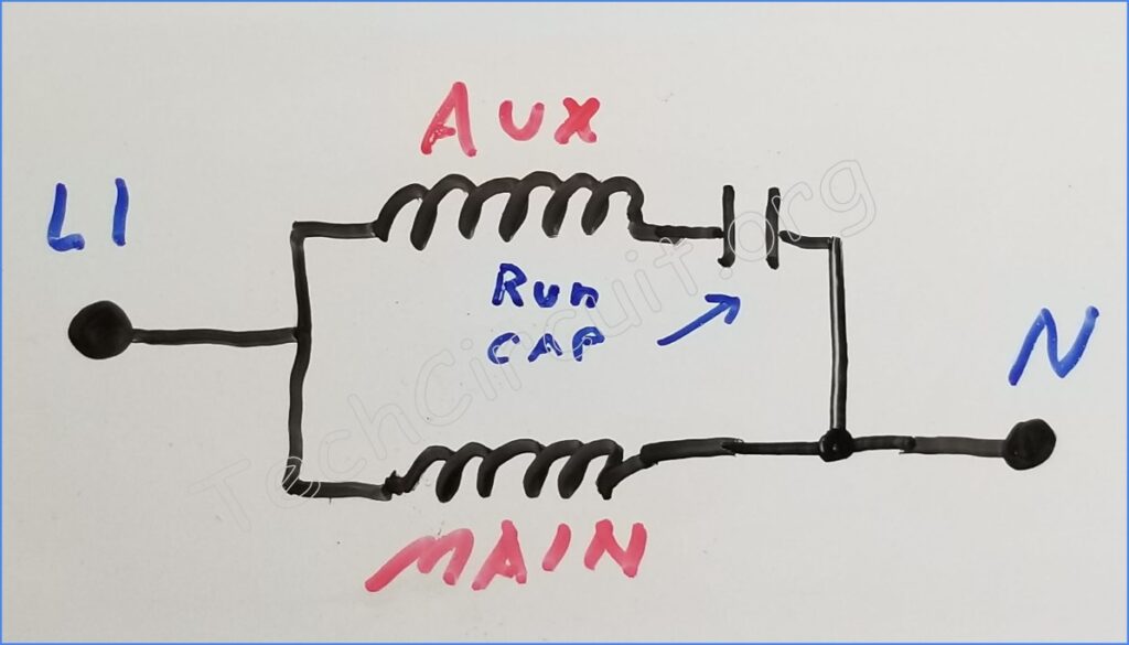
Permanent split capacitor motors use a “run-capacitor”, which accomplishes the same phase shifting task as the capacitor start motor, but with less of a phase-shift. It also leaves the phase-shifting capacitor in circuit (with no centrifugal switch). This lower phase shift is largely due to the capacitor’s small size (in microfarad), relative to that of capacitor start motors. This gives the motor less starting torque (because of the smaller phase shift), but smoother rotational motion at full speed, since the capacitor stays in-circuit. Another benefit to split capacitor motors is that the run capacitor incidentally improves the power factor of the motor. Poor power factor is one of the inherent disadvantages of substantially inductive loads, like induction motors, and is covered in another blog.
Test your Practical Knowledge of Single-Phase Induction Motors!
Understanding Single-Phase Induction Motors
Select the best answer for each question.
Summary
In this article, we discussed how single phase induction motors use start windings, centrifugal switches, and phase shifting to start the motor’s armature. We started off by describing the basics of induction motors, such as how conductive bars are used to induce a magnetic field in the armature, and how slip is required to create a relative speed difference between the stator and the armature. Single phase induction motors were then introduced, with a discussion of how they inherently have a problem with only causing oscillation instead of rotation. The article then covered different types of multi-phase current induction motors, such as capacitor start motors, split phase motors, and split capacitor motors, and how they use different methods to create a rotating magnetic field. The article also explained how centrifugal switches are used in conjunction with some of the described motor types, to remove start windings from the circuit once the motor has reached a specific RPM. Finally we touched on “power-factor”, which amounts to a significant downside of induction motors, and how run capacitors effectively work to correct its detrimental effects, resulting is more efficient operation.
Here is a related video about single phase induction motors:
Don’t forget:
“Diverting 10 min/day of social media time towards learning something new, is 5 hours of newfound monthly knowledge.” – SM
To DONATE to the Tech Circuit – CLICK HERE
Alphabetical Links to all Tech Circuit Articles and Blogs – CLICK HERE
Links to all Tech Circuit Cheat Sheets/Field References for Appliance/HVAC Techs – CLICK HERE
For additional electrical and electronics learning material for field techs, visit our homepage at http://www.TechCircuit.org or our Facebook group at https://www.facebook.com/groups/746823709133603.