Intro to Reading Schematics – A Basic Whirlpool Electric Dryer
This article will schematically show where voltages appear in a Whirlpool Dryer circuit for different operating modes and failure states. This information can be useful to technicians that want to use voltage checks in addition to their other troubleshooting methods. Please note that this article is intended for experienced appliance Technicians only. Please do not work on live circuits unless you are qualified to do so and take appropriate safety measures.
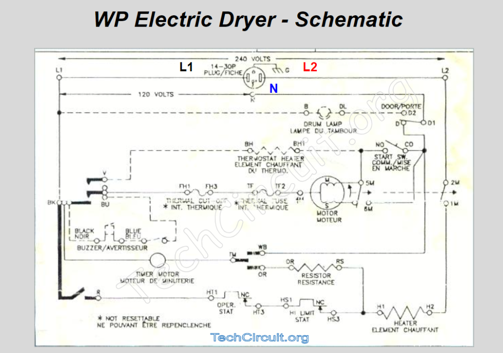
A common and simple Whirlpool Electric Dryer Schematic is shown below.
Be sure to subscribe to our Youtube Channel!
For tons of videos on electrical and electronics diagnostics, practical electrical theory, and field-technician resources, click the picture below or this link here: https://www.youtube.com/@TheTechCircuit?sub_confirmation=1

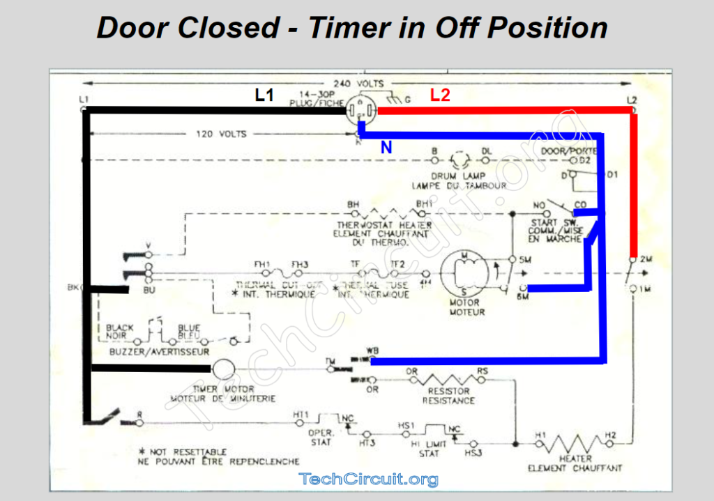
Door Closed – Timer in Off Position
With the dryer plugged in to a 240V outlet, you can expect to see the following voltage paths where black denotes L1, red is L2, and blue is Neutral. L1 and L2 are 240V with respect to each other. L1 and L2 are 120V with respect to Neutral, but are of opposite polarity.
CLICK HERE TO SEE THE GAS DRYER SCHEMATIC WALKTHROUGH
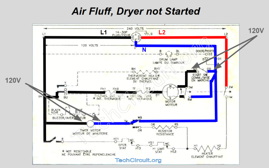
Air Fluff – Dryer not Started
Now with the timer advanced to Air Fluff mode and the dryer not yet started. L1 makes its way through the motor windings to the left side of the start switch. Neutral is still on the right side of the start switch but now continues through timer contacts TM and WB to the right side of the timer, which now has 120V across it.
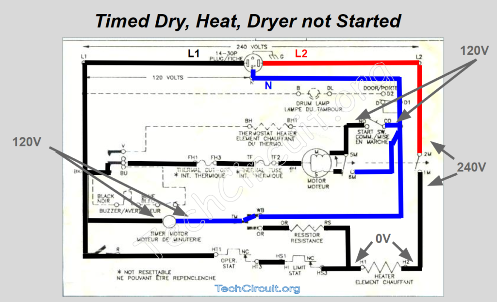
Timed Dry – Heat – Dryer not Started
When the timer is advanced to timed dry, the voltage paths change when timer contacts BK and R close causing L1 to travel through all elements up to the bottom of the motor’s centrifugal switch. Note that there are no voltage drops across any of those elements because there no closed circuit yet and thus no current flow.
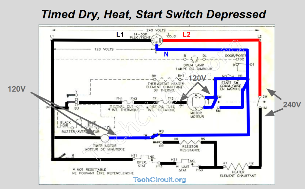
Timed Dry – Heat – Switch Depressed
At the moment the start switch is depressed but the has not reached enough speed to trip the centrifugal switch, the voltages will appear as below. Note that the full 120V appears across the motor via L1 on the left and both the start and main windings. At this moment, the start winding gives the motor some phase-shifted directional guidance with respect to the main winding to start motor rotation. At this point, because the centrifugal switch has not yet tripped, the voltage across the heat circuit side of the centrifugal switch is still 240V and not current is yet flowing through the heating element.
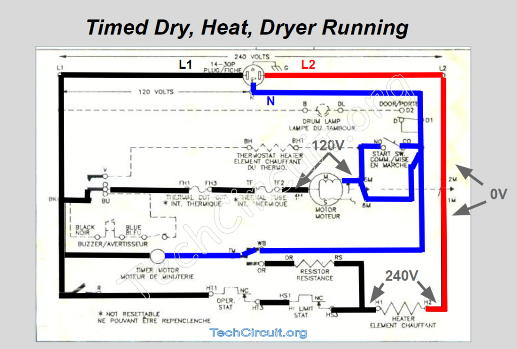
Timed Dry – Heat – Dryer Running
Once the centrifugal switch has tripped at about 3/4 full motor speed, the start winding is no longer energized as below. The motor’s momentum, along with the main winding’s 180 degree North to South shift on each half cycle, keep the motor rotating. Note also that the centrifugal switch is now closed and 0V appears across it, current is flowing through the heating circuit, and the heating element is energized with the 240V difference between L1 and L2.
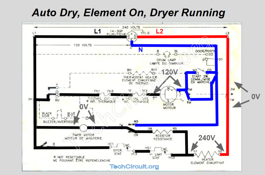
Auto Dry – Element Energized – Dryer Running
On this particular model, auto-dry only advances the timer when the element is cycled off by the thermostat. When the element is energized, the timer stops advancing. This is accomplished by feeding L2 back through the element through a resistor and to the right side of the timer. When the element is on, however, the voltages appear as below with no voltage to the timer.
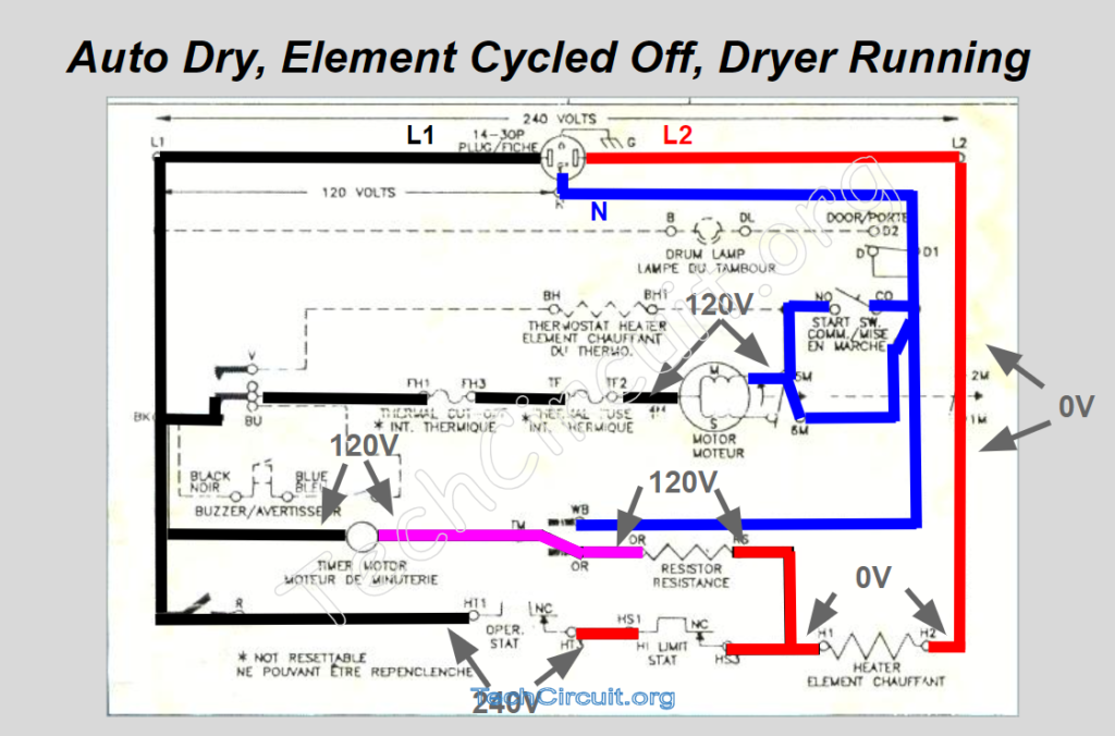
Auto Dry – Element Cycled Off – Dryer Running
When the element cycles off, 240V appears across the cycling thermostat because L2 goes right through the element and also to the right side of the resistor – across which 120V is then dropped – leaving 120V to the right side of the timer with respect to L1. The timer now advances until the cycling thermostat closes – and the cycle repeats.
CLICK HERE TO SEE THE GAS DRYER SCHEMATIC WALKTHROUGH
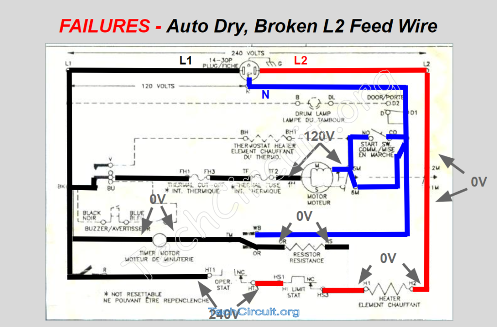
Auto Dry – Broken L2 Feed Wire
The remaining images show common failures and associated voltage paths for this dryer. During auto dry, if the wire that connects from the heating element to the timer is broken, the dryer will run continuously – cycling the heat on and off until the timer is manually advanced by the user.
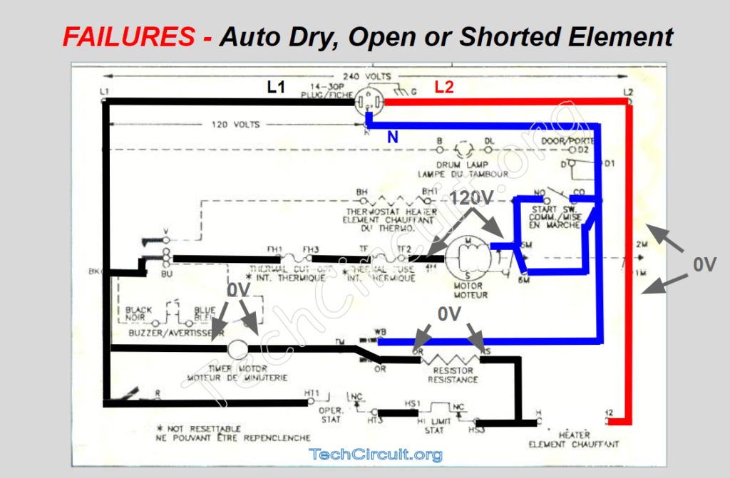
Auto Dry – Open or Shorted Element
Next, in auto-dry mode, with an open or even shorted element, L2 fails to appear on the left side of the element and can no longer supply voltage to the right side of the timer motor through the resistor. The customer complaint will be that the dryer will run forever without heat in both the auto dry mode or in the cool-down portion of timed dry.
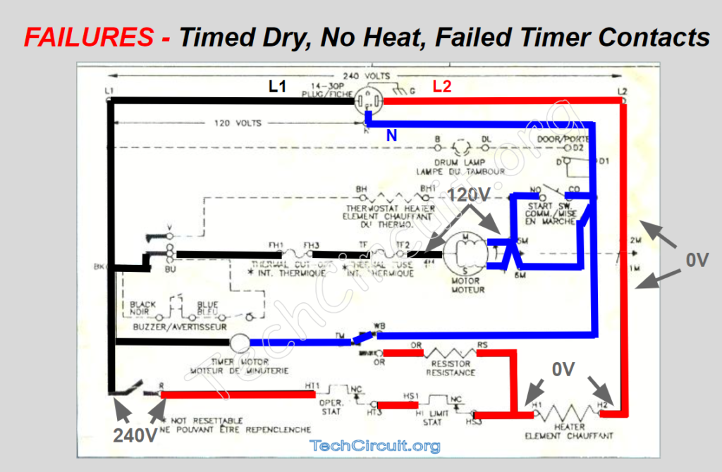
Timed Dry – No Heat – Failed Timer Contacts
Next, one of the most common symptoms with this model of dryer – no heat. The next voltage map shows what would happen if the BK – R timer contacts fail. This is a common cause as a lot of current flows through those contacts – generating a significant amount of heat – which can accelerate their failure.
Timed Dry – No Heat – Failed Centrifugal Switch
Next, the voltage map for the same symptom – no heat, with a failed centrifugal heat circuit switch. In this case, the centrifugal switch for the heat circuit isn’t closing and still has 240V across it. No voltage appears on the right side of the element and no current will flow. You can easily check this by testing the voltage from L2 to the element – if you get 240V, your centrifugal switch and thus your motor – has failed.

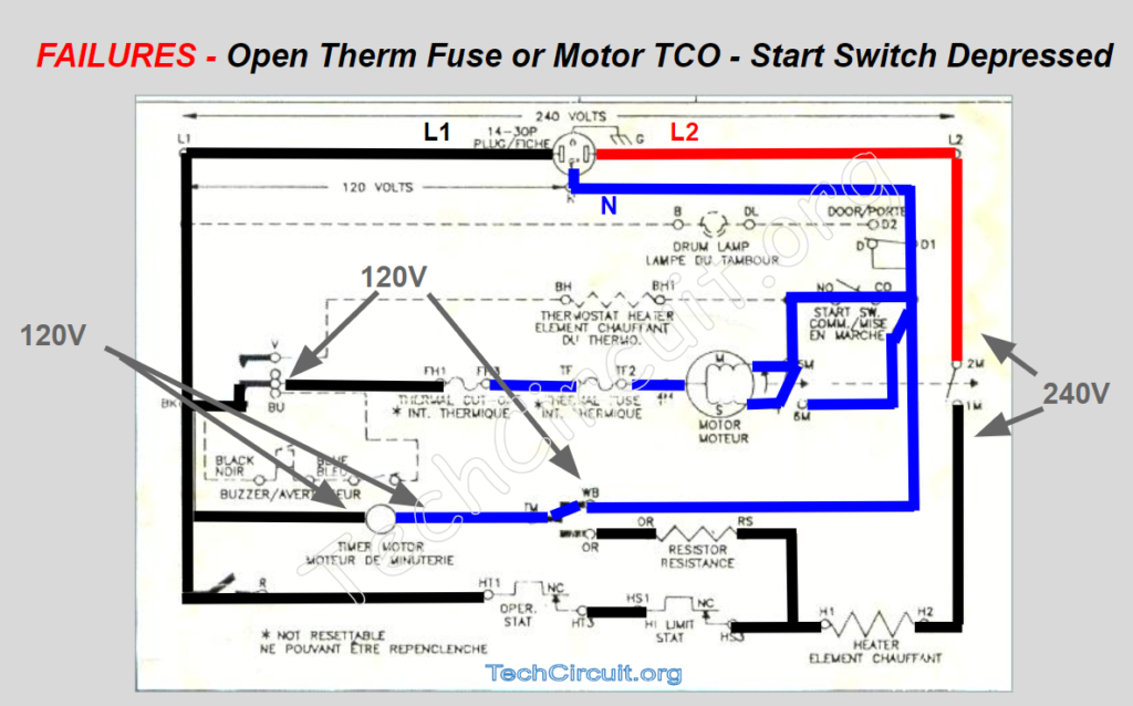
Open Thermal Fuse or Motor TCO – Start Switch Depressed
Another common symptom is that the dryer won’t start. This is often caused by the thermal fuse. If so, your voltage will look as follows. You can check this from the console by measuring the voltage between BK and BU when the dryer is set to a cycle and the start switch is pressed down. This will tell you that you either have an open thermal fuse or failed motor.
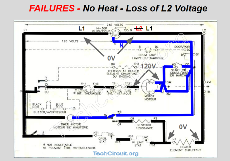
No Heat – Loss of L2 Voltage
Finally, when this dryer is running in heat mode and the L2 leg of the line voltage is lost, L1 travels through the heating element and centrifugal switch, appearing at the same location where L2 is wired to the terminal block. In this case, you will read approximately 0V from L1 to L2 when the dryer and element are putting a load on the circuit. Technicians that use Neutral as a reference can get confused because they see 120V from Neutral to both L1 and what they think is L2, but they are actually reading L1 on both sides of the block.
A great multimeter for appliance repair is the Klein CL800. It has just about every function you’ll ever need. Purchasing the Klein CL800 from by clicking the picture below helps support our goal to further educate Appliance and HVAC technicians in the area of electricity and electronics.

Below is a video with a full description and walk-through of the above described scenarios. Also visit our Facebook Group at https://www.facebook.com/groups/746823709133603/
CLICK HERE TO SEE THE GAS DRYER SCHEMATIC WALKTHROUGH
Alphabetical Links to all Tech Circuit Articles and Blogs – CLICK HERE
Alphabetical Links to all Tech Circuit Cheat Sheets/Field References for Appliance/HVAC Techs – CLICK HERE
Don’t forget:
“Diverting 10 min/day of social media time towards learning something new, is 5 hours of newfound monthly knowledge.” – SM
To donate to the Tech Circuit – CLICK HERE
For additional electrical and electronics learning material for field techs, visit our homepage at http://www.TechCircuit.org
or our YouTube Channel at https://www.youtube.com/c/TheTechCircuit
or our Facebook group at https://www.facebook.com/groups/746823709133603.
We are a participant in the Amazon Services LLC Associates Program, an affiliate advertising program designed to provide a means for us to earn fees by linking to Amazon.com and affiliated sites.