
Introduction – A Basic Whirlpool GAS Dryer
This article will schematically show where voltages appear in a Whirlpool GAS Dryer circuit for different operating modes and failures. Aside from being a valuable educational tool, this information can be useful to technicians that want to use voltage checks in addition to their other troubleshooting methods. Please note that this article is intended for either supervised or experienced Appliance Technicians. Please do not work on live circuits unless you are qualified to do so and take appropriate safety precautions.
For a detailed walkthrough of just the gas valve ignition circuit and associated failures, click here: https://techcircuit.org/whirlpool-gas-dryer-ignition-circuit-step-by-step/
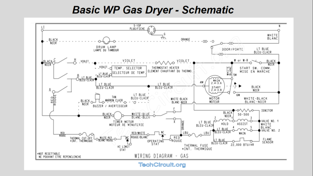
A non-energized, common, and basic Whirlpool Gas Dryer schematic is shown below.
CLICK HERE TO SEE THE 240V ELECTRIC DRYER SCHEMATIC WALKTHROUGH
Be sure to subscribe to our Youtube Channel!
For tons of videos on electrical and electronics diagnostics, practical electrical theory, and field-technician resources, click the picture below or this link here: https://www.youtube.com/@TheTechCircuit?sub_confirmation=1

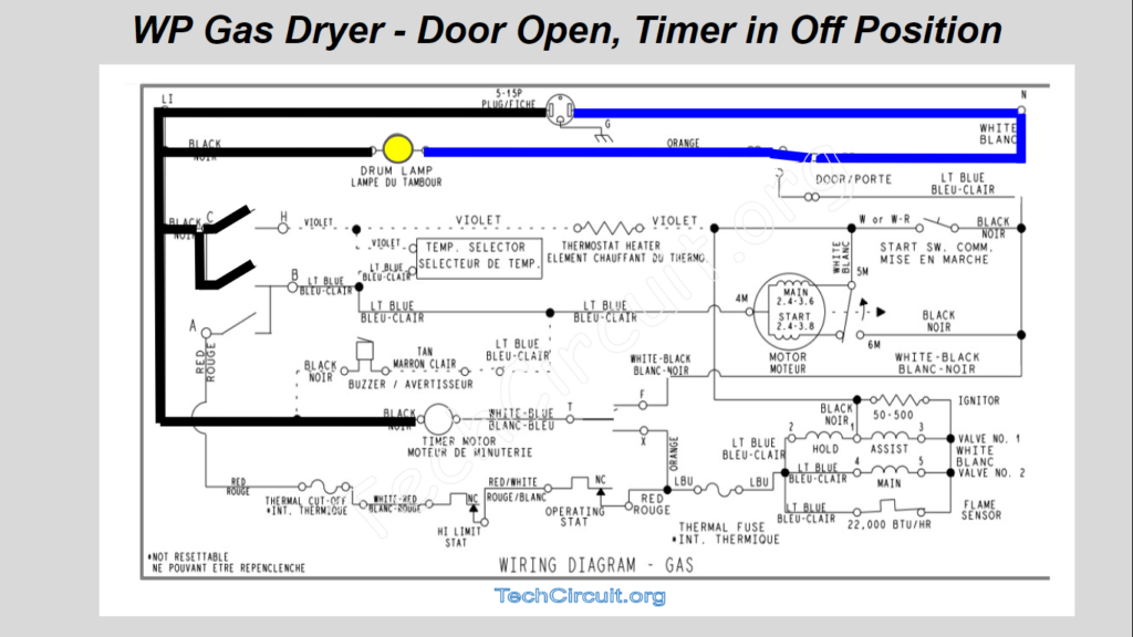
Door Open – Timer in Off Position
With the dryer plugged in to a 120v outlet, you can expect to see the following voltage states where black denotes L1 and blue is Neutral. 120v from L1 makes its way to the left side of the drum light and the timer motor as shown. The door switch allows neutral to appears at the right side of the drum light, causing the light to illuminate – as shown below:
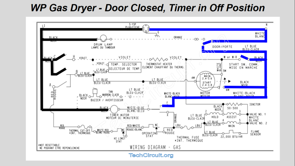
Door Closed – Timer in Off Position
When the door is shut, the door switch diverts Neutral from the drum light to the motor circuit. The light goes out, and Neutral appears at the right side of both the start switch, and the motor’s open centrifugal switch. As shown below:
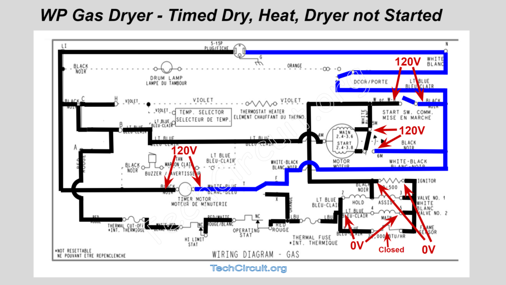
Timed Dry – Heat – Dryer not Started
After advancing the timer to timed dry, the voltage states change when timer contacts C-H, C-B, and A-B, close – causing L1 to make its way to the left side of the drive motor, and the left side of the timer motor. Also, L1 passes through the thermal components, the radiant sensor (which is closed), the coils, the ignitor, and ultimately shows up at the left side of the start switch and to the left side of the centrifugal switch. Since the centrifugal switch is still open, there is no closed circuit and thus no current yet flowing through the motor or heat circuit. Shown in the image below:
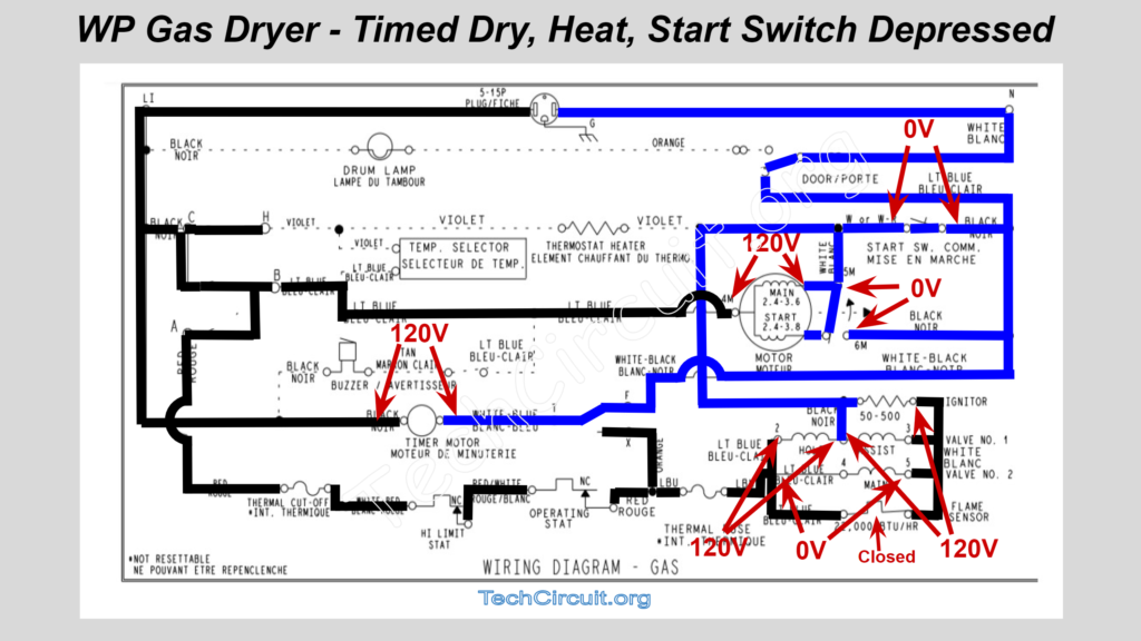
Timed Dry – Heat – Start Switch Depressed
At the moment the start switch is depressed, but the motor has not gained enough RPM to flip the centrifugal switch, the voltages will appear as below. Note that the motor now has 120v across both the start and main windings. In this moment, the start winding provides phase-shifted directional guidance (with respect to the main winding), in order to start motor rotation. Since the radiant sensor is till closed, Neutral now appears at the left side of the ignitor, causing 120v to appear across that ignitor, which starts to glow. Note also that both the hold and assist coils each have 120v across them, causing the first valve solenoid to open. The main coil has 0 volts across it because it is “shunted” by the closed radiant sensor – as depicted below:
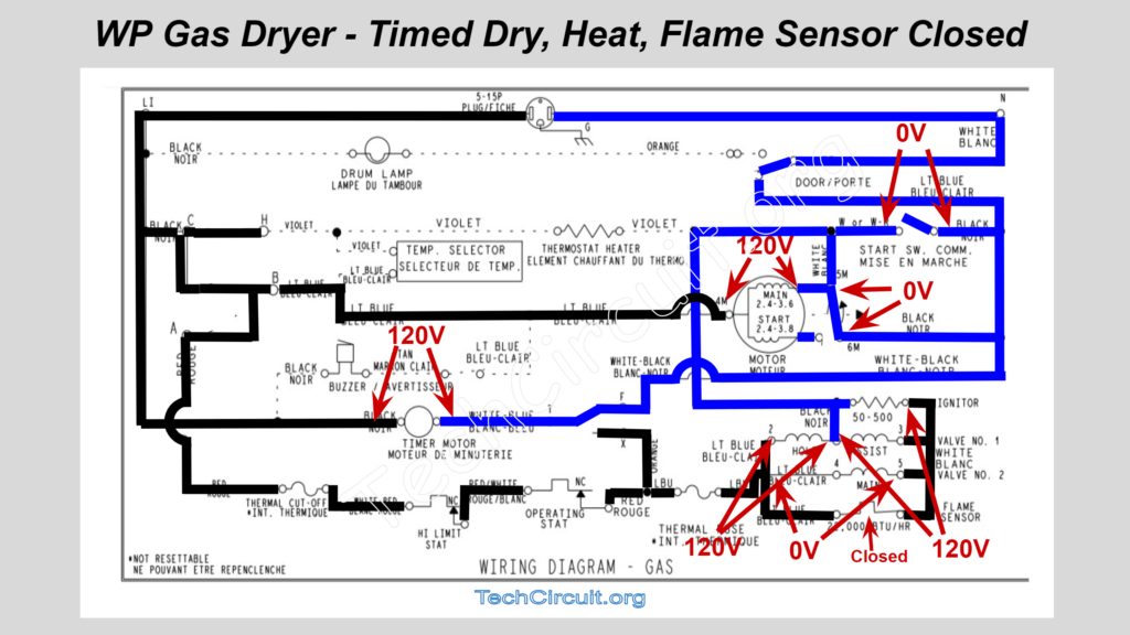
Timed Dry – Heat – Dryer Running – Flame Sensor Closed
This state only occurs for 5-10 seconds after the start switch was depressed. The only difference here is in the motor circuit – that the start switch is now open, but the centrifugal switch is now flipped as the motor has reached its running RPM. As such, that centrifugal switch now continues to provide the same Neutral potential to the left side of the ignitor that was provided by pressing the start switch – and the start switch is now no longer needed to maintain Neutral at the motor. The flame sensor is still closed because the radiant heat from the glowing ignitor hasn’t yet caused it to open. The first gas valve solenoid has been open since the pressing of the start switch, but the main valve is still closed because it is still shunted by the radiant sensor – as shown below:
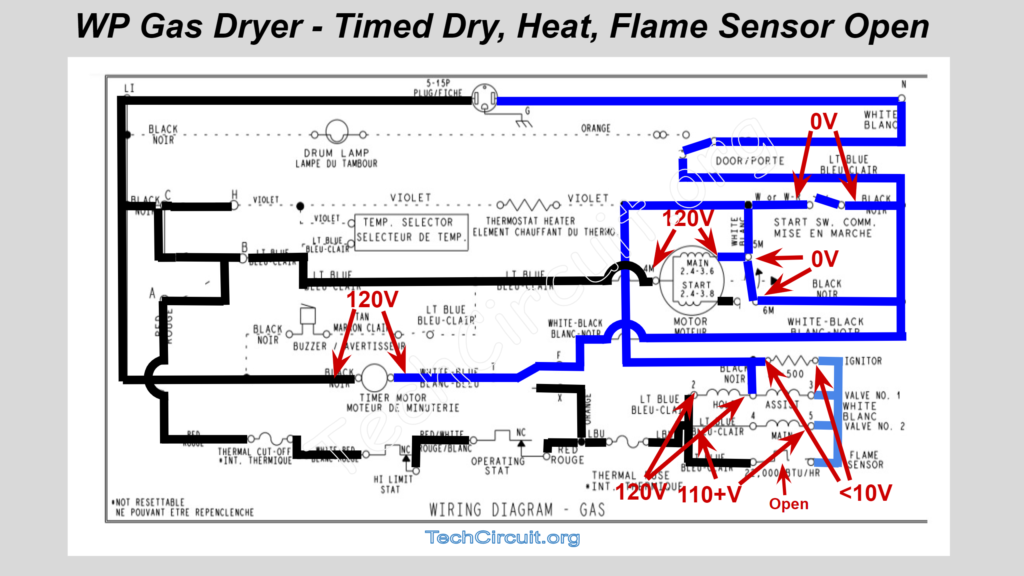
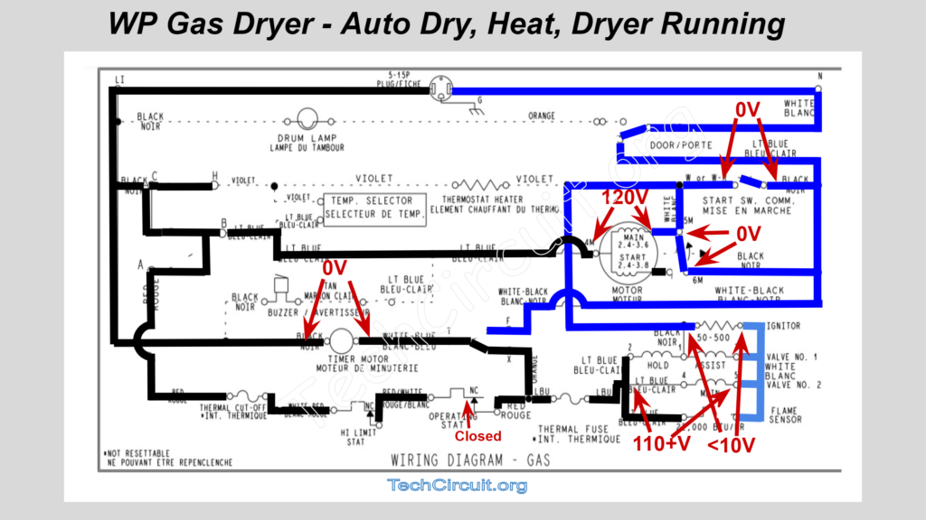
Timed Dry – Heat – Dryer Running – Flame Sensor Open
This is the target functional state of the dryer’s heat circuit. The flame sensor has now opened. Prior to that, it was acting as a shunt to disallow voltage from appearing across the main coil. Now that it is open, voltage does now appear across the main coil. The 2nd solenoid now opens, and gas starts flowing and is ignited from the still glowing ignitor. The assist coil looses its voltage, but the hold coil still has 120v across it. As such, it “Holds” the first solenoid open as long as it stays energized. The ignitor no longer is energized, but the radiant heat from the flame itself keeps the sensor open. Note that the ignitor has a very low resistance as compared to that of the coils (small inductive reactance ignored). Thus a voltage divider is formed where the ignitor has a very low voltage across it – allowing the bulk of the line voltage to appear across the coils and keep them energized. Thus less than 10v will appear across the ignitor (and assist coil) and greater than 110v across the main coil. As shown:
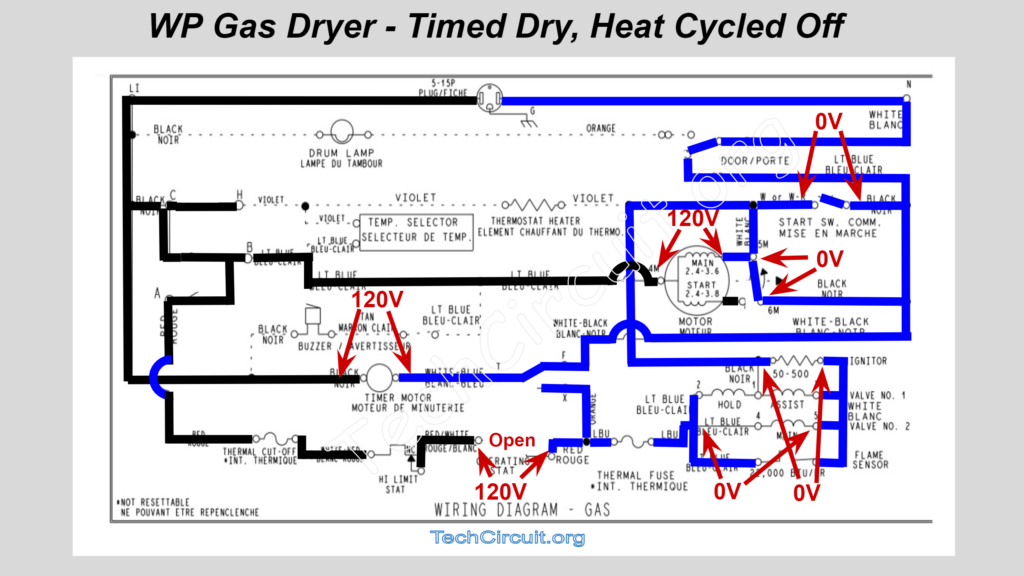
Timed Dry – Heat – Dryer Running – Heat Cycled Off
Once the operating thermostat reaches its “cut-off” temp, it will open up and L1 will no longer appear at the left side of the gas circuit. In fact, Neutral now makes its way through the gas circuit and appears on the right side of the operating thermostat – causing there to be a voltage difference of 120v across that thermostat. With the gas circuit now deenergized, both the ignitor and coils loose voltage and the gas valve closes – stopping the gas flow. As the dryer cools down, it will eventually allow the cycling thermostat to “cut-in” and re-energize the gas circuit, which will go through its aforementioned sequence to detect the ignitor, energize the coils, and open the valve. As shown in the image below:
CLICK HERE TO SEE THE 240V ELECTRIC DRYER SCHEMATIC WALKTHROUGH
Auto Dry – Heat Circuit Cycled On – Dryer Running
In this special mode, the timer contacts T and F are no longer connected, and rather T and X are now closed. This allows the voltage state on the right side of the cycling thermostat to dictate whether the timer motor has voltage across it. While the heat is cycled on, the operating thermostat is closed. This means that L1 appears on its right side, as well as on the left side of the timer motor. However, since the left side of the timer motor also has L1, the voltage difference is zero – meaning that the timer motor is not energized and not advancing the timer. This is depicted in the image below:
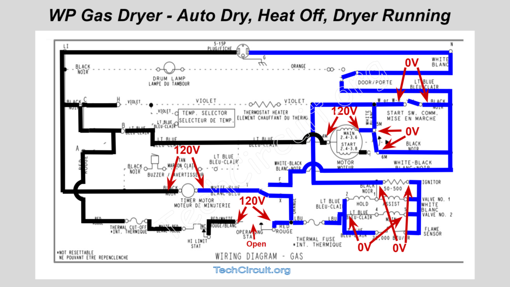
Auto Dry – Heat Circuit Cycled Off – Dryer Running
Once the heat cycles off, L1 no longer appears on the right side of the operating thermostat. In fact, Neutral appears at that point as it has made its way through the heat circuit. It also appears on the right side of the timer motor, causing the voltage difference across it to be approximately 120v (N-L1). There is a slight voltage drop across the ignitor, but its resistance is so low, this voltage is negligible. So the timer motor runs, and advances the timer when the heat cycles off. This operation causes the timer to only advance when the dryer has reached its peak temperature. As the load of clothes become drier, and its resulting thermal mass decreases, the peak temperature is reached more quickly – causing the timer to advance more quickly toward the end of the cycle. As shown below:
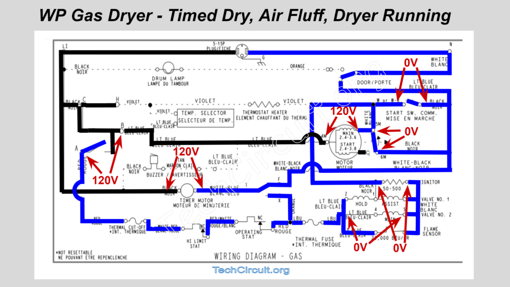
Air Fluff – Dryer Running
In this mode, the timer is simply not passing L1 to the heat circuit. Contacts A and B are open, which breaks that circuit. In this case, 120v will appear across those contacts (A and B). Shown in image below:
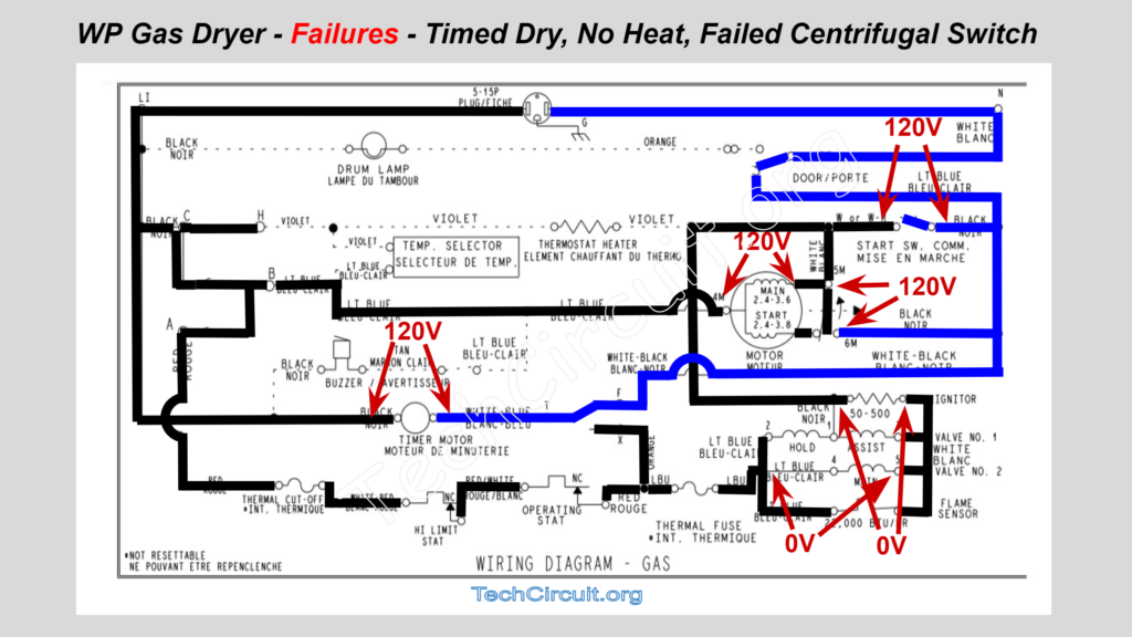
Failures – Timed Dry – No Heat – Failed Centrifugal Switch
In the case of a failed centrifugal switch where it doesn’t close and pass neutral on to the heat circuit, the left side of the heat circuit has L1 potential as passed on by timer contacts A and B, but no Neutral at the other side of the ignitor. Thus, the ignitor (and the rest of the heat circuit) has a zero volt potential across it and is disabled. The centrifugal switch will read a 120v potential across it because L1 will make its way through the closed flame sensor and the ignitor to said centrifugal switch. The motor of course won’t continue running once the start switch is released, as the centrifugal switch does not take over the task of providing continuity for the Neutral side of the motor – as shown in the image:
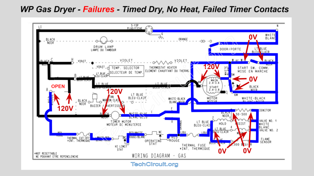
Failures – Timed Dry – No Heat – Failed Timer Contacts
In the case of failed timer contacts where the heat circuit is normally switched, contacts A and B will remain open. L1 will thus not make its way to the left side of the heat circuit. In fact, neutral potential will make its way through the heat circuit, and appear at contact A. Thus the voltage potential difference between contacts A and B will be 120v. This is the same scenario as air fluff in terms of how the voltage states appear – as depicted below:
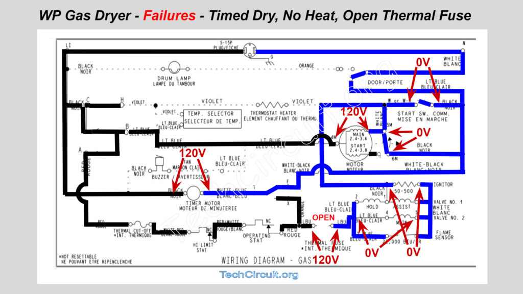
Failures – Timed Dry – No Heat – Open Thermal Fuse
Much like the failed timer contact in the previous case, an open thermal fuse will prevent L1 from making its way to the left side of the heat circuit. L1 will appear at the left side of the thermal fuse though, as the timer is passing it along via contacts A and B. Because L1 isn’t present, neutral will make its way through the heat circuit (the ignitor and flame sensor), and appear on the left side of the thermal fuse. Thus, the thermal fuse will have 120v across it. This is an extremely common failure mode with Whirlpool made gas dryers. As shown below:
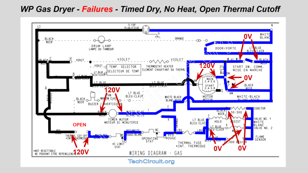
Failures – Timed Dry – No Heat – Open Thermal Cutoff
The scenario of an open thermal cutoff is almost identical to that of the thermal fuse, but the open circuit appears early up the “L1” line – closer to the timer. L1 will stop at the left side of the thermal cutoff and neutral will appear at the right side – causing a voltage potential of 120v to be measured across the cutoff. As shown in the image below:
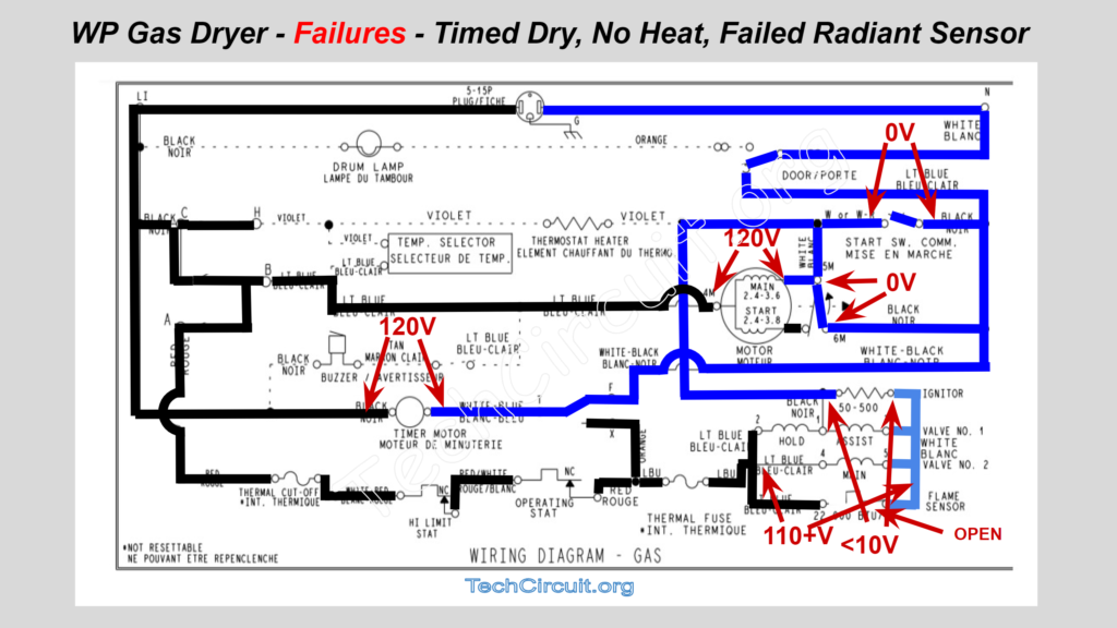
Failures – Timed Dry – No Heat – Failed Radiant Sensor
In this case, L1 will make it to the left side of the radiant sensor and the left side of the main and hold coils. Because of the very low resistance of the ignitor as compared to the main coil, the main coil will get greater than 110v and will open that solenoid. Thus the user will hear the click of the gas valve when pressing start. However, less than 10v should appear across the ignitor (and assist coil), rendering the safety solenoid unable to open and no gas will flow – as shown:
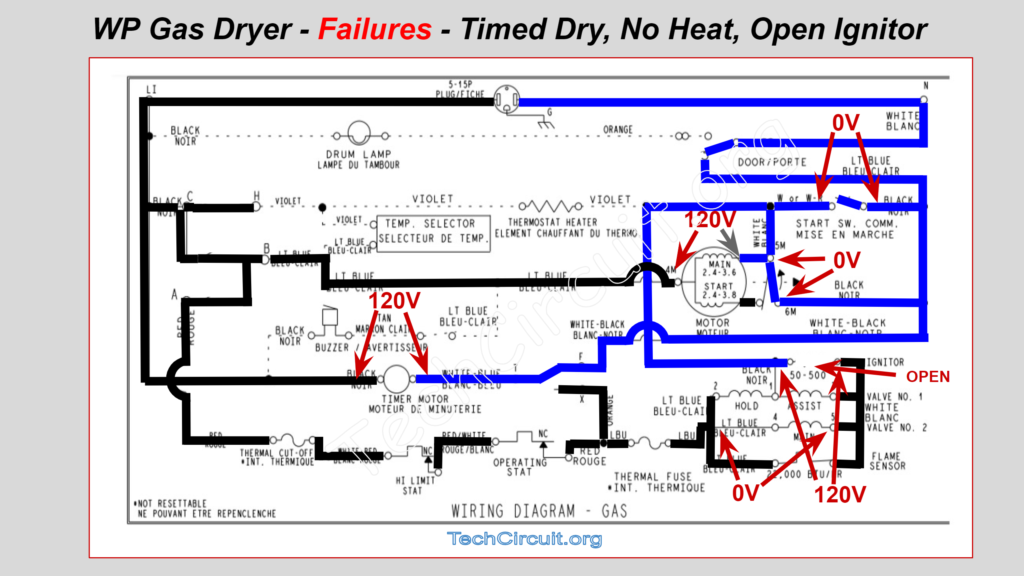
Failures – Timed Dry – No Heat – Open Ignitor
If the ignitor is open, no current flows through it (or the gas valve circuit) at all. Neutral will be on its left side, and L1 (via the flame sensor) will be on the right. 120v will be measured across the ignitor, but it won’t glow. In this case, the user won’t notice any “clicks” of the gas valve assembly since no current is flowing through it. A failing ignitor where its resistance is very high will render similar voltage states and effects on the gas valve circuit – as shown:
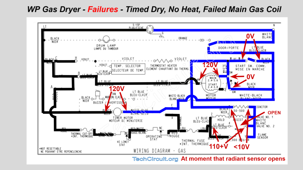
Failures – Timed Dry – No Heat – Failed Main Gas Coil
If the main coil is open, the gas will not flow. The hold and assist coils will open the first section of the valve, but the primary solenoid will not function. This renders the gas valve unable to operate. In this case, 110 + volts will appear across the main valve once the flame sensor opens, but will quickly go back to 0v after the ignitor cools down and closes said flame sensor. This condition will cause the heat circuit to open and close in an oscillating fashion about once every 5 – 10 seconds. The user will report hearing the gas valve assembly correspondingly “click” at that rate. This is depicted in the image below. Intermittently failing coils often cause the gas valves to close inappropriately. If the user reports intermittent operation or that the dryer heats initially, but stops heating, it is likely one of the coils has warmed up, internally expanded, and has lost continuity. This is extremely common, and thus replacing the low-cost and readily accessible coils is recommended for any such complaints:
Video Version of the GAS Dryer Schematic Walkthrough
CLICK HERE TO SEE THE 240V ELECTRIC DRYER SCHEMATIC WALKTHROUGH
Special thanks to David B. Hinton of DBH Appliance Repair in Dyer, Indiana, for his experiential input into this article.
I hope that you found this article educational and informative. Articles like this take a tremendous amount of time to compile. If you have found this helpful, please consider donating the the Tech Circuit:
To donate to the Tech Circuit – CLICK HERE
For additional electrical and electronics learning material for field techs, visit our homepage at http://www.TechCircuit.org
or our YouTube Channel at https://www.youtube.com/c/TheTechCircuit
or our Facebook group at
https://www.facebook.com/groups/746823709133603.