What does it mean when we say “Ohms can Lie”? It’s more of a colloquial expression suggesting that relying on static resistance may not give you enough information about how some components behave when energized. For example, when you measure the resistance of a component, and its “opposition to current flow” varies when subjected to current, your initial static measurement didn’t completely reflect the component’s behavior within a circuit.
Now on to some specific examples of how “ohms can lie”.
Be sure to subscribe to our Youtube Channel!
For tons of videos on electrical and electronics diagnostics, practical electrical theory, and field-technician resources, click the picture below or this link here: https://www.youtube.com/@TheTechCircuit?sub_confirmation=1

1. Measured Resistance vs. Impedance
Like resistance, impedance is the opposition to current flow, but when AC current is involved. Impedance can be resistance, the effects of capacitance, the effects of inductance, or any combination thereof. Solenoids and motors are commonly encountered examples of how impedance can cause a very different amount of current to flow than your static resistance readings would lead you to believe.
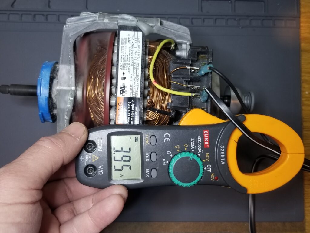
Induction Motor
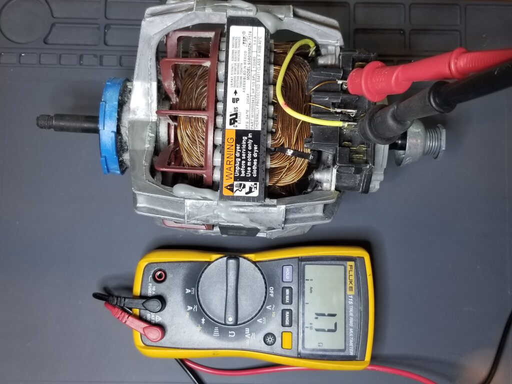
Lets take a common induction motor (like a dryer motor) for example. The measured resistance of the windings can be as low as a few ohms. Straight Ohm’s law would imply that at 120 volts, your current would be 120v / 2Ω = 60 amps – and we know that’s not right. Most dryer motors don’t draw more than 5 amps. An average current draw is around 4 amps. So why is it so low? Because of the winding’s inductive reactance, which along with the winding’s resistance, makes up the total impedance of the motor. Finding the impedance is complex (especially for motors), but It comes out to about 30Ω when under a normal mechanical load, which is 15 times higher than the measured 2Ω.
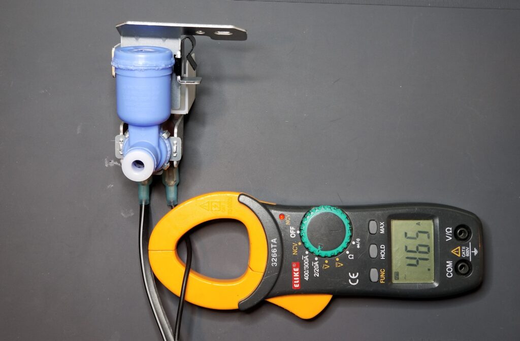
Solenoids
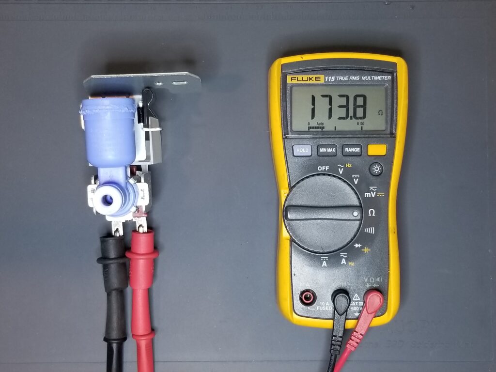
Solenoids, such as inlet valves, are inductors and present inductive reactance that changes their opposition to current flow when AC voltage is applied. A common refrigerator inlet valve solenoid measures about 170 ohms of resistance with a multimeter. However, the inductive reactance of the coil increases the overall impedance of about 265 ohms. This is much higher than what your meter read during your static test. Thus, instead of seeing about (120v / 170Ω) = 0.71 amps, based on your static reading, you will see (120v / 265Ω) = 0.46 amps. Thus your static reading was not representative of how much current would flow through that solenoid once energized.
Click the Image Below to Purchase the Fluke Multimeter
2. Temperature Coefficients
Most materials change resistance when hot. Materials that increase in resistance with temperature, have a positive temperature coefficient (PTC), and those that decrease in resistance have a negative temperature coefficient (NTC).
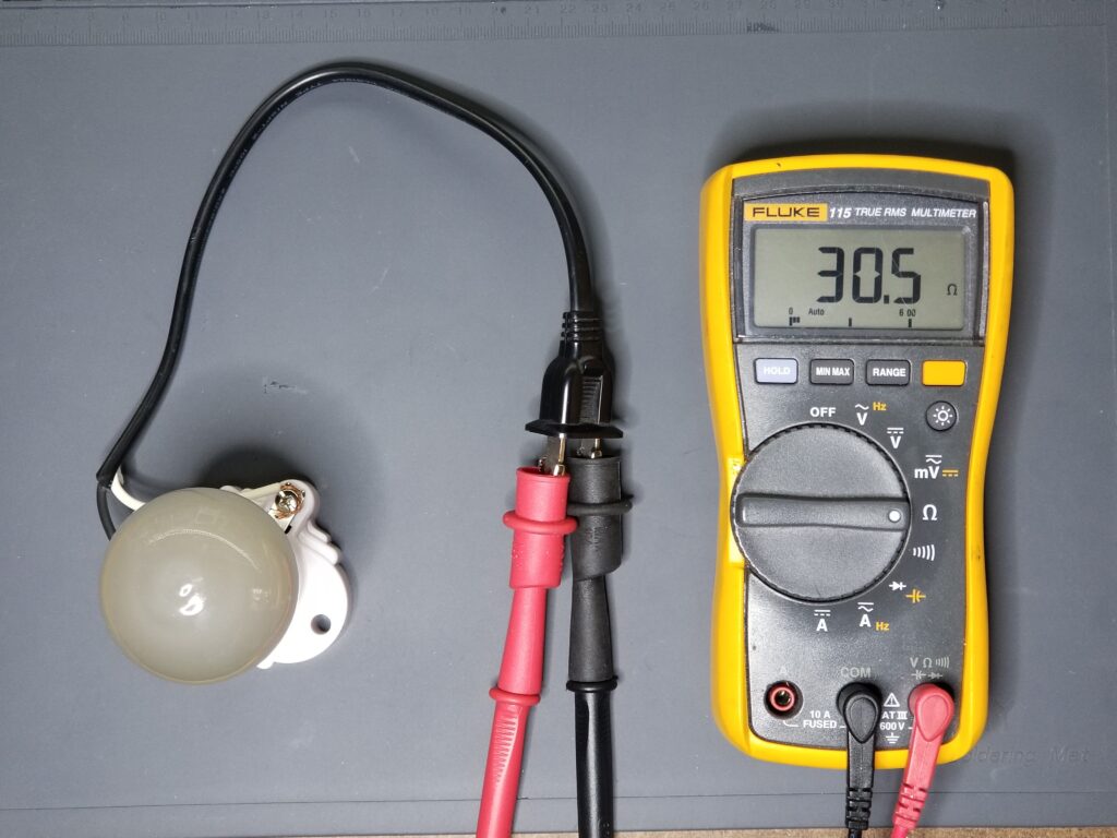
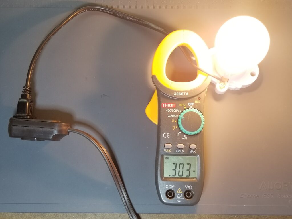
Incandescent Bulbs
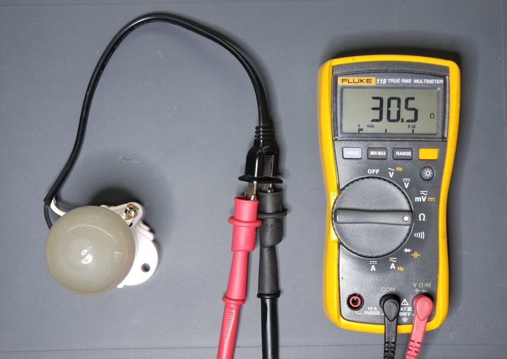
Incandescent bulbs are a perfect example of how heating can cause drastic resistance changes. In a 40w incandescent bulb, the tungsten element can measure 30 ohms with your multimeter. However, when you energize the bulb, it may only draw about 1/3rd of an amp. At that current draw, the effective resistance of the bulb has increased to 120v / 0.3A = 400Ω. This is a 13-fold increase in the “ohms” you measured with your multimeter. An incandescent bulb is a PTC device, by the way.
Gas Ignition Ignitors
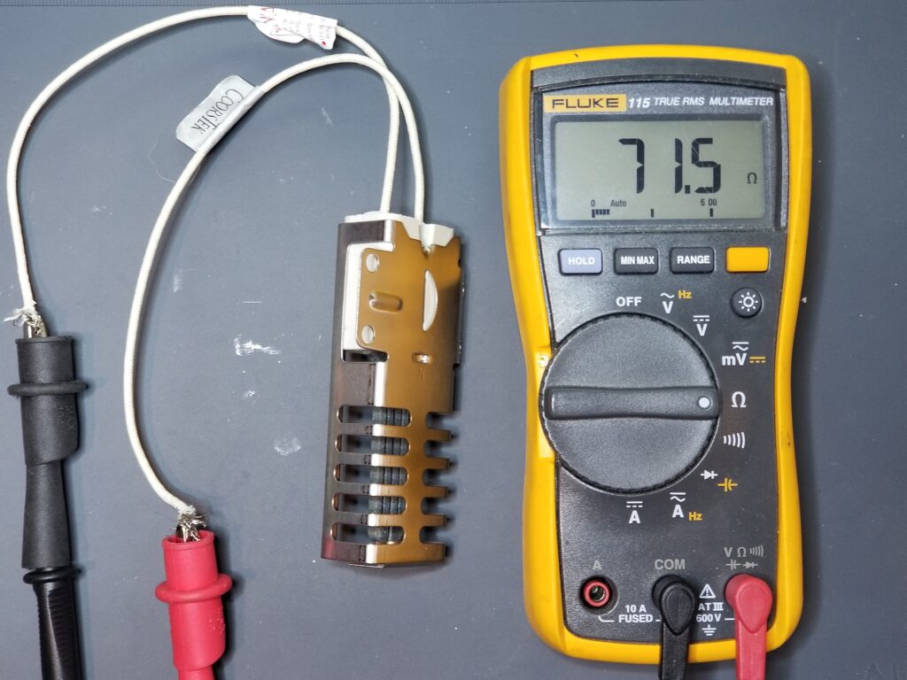
Many glow ignitors, such as those used in conventional gas ovens, are NTC devices. That is, their resistance decreases as they heat up. This is by design. As their resistance decreases, the current through them increases, and correspondingly, so does the current through the safety valve – which is in series with the ignitor. That increased current, which is an indication that the ignitor has reached its correct temperature, causes the safety valve to open and let the gas flow. A typical square oven ignitor may measure around 70 ohms when measured with your multimeter – which, based on Ohm’s law, would imply a 120v/70Ω = 1.7 amp draw. However, the current flowing through that ignitor at ignition (greater than 3.2 amps), implies that it decreases to 120v / 3.2 amps = 38 ohms. That’s about 1/2 of the measured value. Thus your initial static measurement of that ignitor didn’t tell you much about the device – other than that it wasn’t open.
3. Voltage Breakdowns and Thresholds
Sometimes current will only flow when a certain voltage potential is reached. This is true of insulation breakdowns, semiconductors, and specific devices, such as MOV (Metal Oxide Varistors), to name a few.
Insulation Breakdown
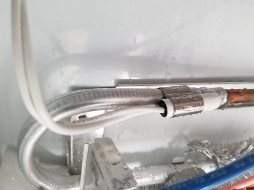
Electrical insulation can break down once a certain voltage potential is applied. After this threshold is reached, there can be a precipitous increase in current flow. One example is that of a refrigerator compressor that is tripping a breaker when it is energized. Resistance measurements, however, may not provide any useful readings – because the voltage level used by the meter is only a few volts – not nearly enough to cause an insulation breakdown. When the compressor is energized, however, the 120 volt potential with respect to ground (at one end of the windings) is enough to cross that “threshold” of current flow, and trip the breaker.
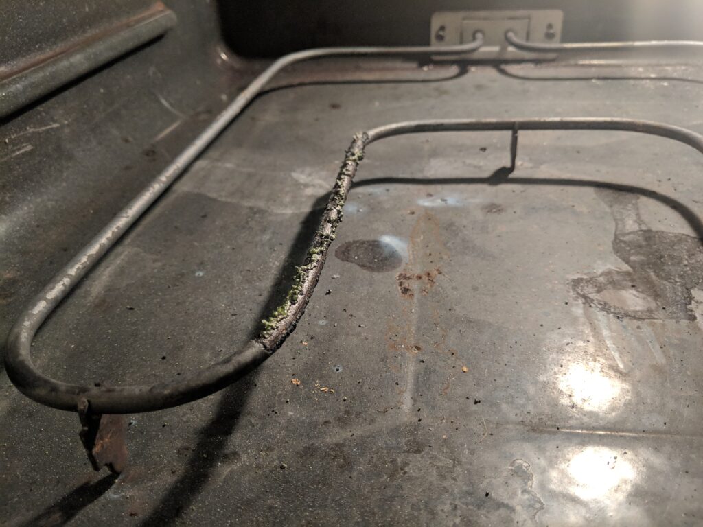
Oven bake elements are another example of how ohms can lie in this respect. The outer covering of bake elements is conductive, and grounded to the oven. When the insulation breaks down, the oven can trip the breaker. However, a static measurement between ground and the oven terminal can give an “infinite resistance” reading. Thus, no useful information would be provided with that test – another example of how insulation breakdowns can fool Technicians.
Fortunately, a type of resistance tester called a “megger”, can be used to detect such breakdowns. It uses voltages as high as 1000v in its resistance measurements, which readily reveals such insulation breakdowns.
Intermittent Thermistors
It’s also worth mentioning that thermistors such as those in dryers, ovens, and refrigerators can behave erratically when subjected to their target environment. In fact, many Technicians are familiar with having found them to statically measure within their specified range, only for them to break down when under stress.
Semiconductors
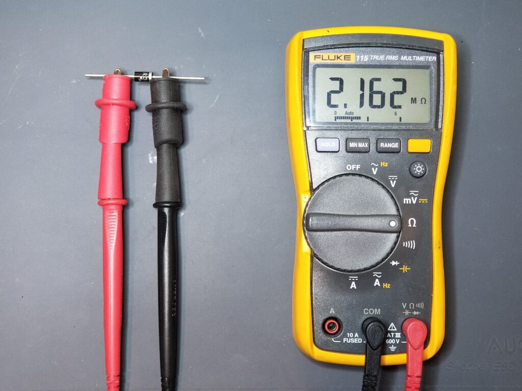
Semiconductors like diodes and transistors are non-linear devices. That is, the current that flows through them isn’t consistently a function of the voltage applied. A diode is a great example. If you measure a diode with an ohmmeter, you’ll either read an open circuit, or an extremely high resistance. However, when a diode is in circuit and conducting, it looks almost like a wire or a short (less some voltage drop).
A semiconductor needs a certain voltage across it before it starts conducting. Until you reach that voltage threshold, no current will flow. Microwave diodes are a prime example of this. In fact, most testing methods for those diodes, involve a voltage source, like a 9v battery that provides enough voltage to forward bias the diode.
Transistors, triacs, and FETs, are likewise non-linear devices that require voltage “biasing” before current can flow through them – and can’t generally be tested using “ohms”.
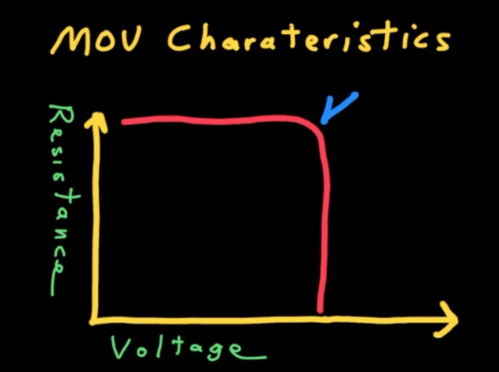
MOVs (Metal Oxide Varistor)
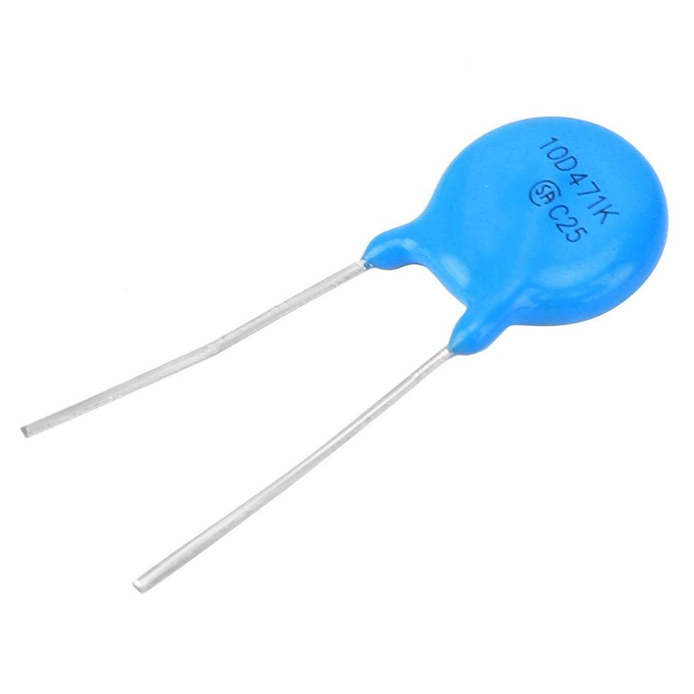
This device intentionally has a high resistance until it reaches a voltage threshold. By design, it allows virtually no current to pass through it until it reaches a predetermined voltage (like 400v). This is used to protect power supplies and other sensitive equipment, as well as dampen inductive spikes by solenoids and relays. A “megger” as mentioned earlier would easily be able to detect the voltage threshold of such devices. Unless such an MOV is damaged and/or shorted, a run of the mill resistance test won’t reveal anything useful about it.
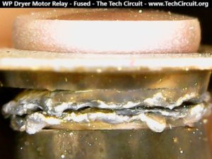
4. Non Linear Contact Resistance
Some components, such as switches and relays use “contacts” that are forced together in order to make contact and conduct electricity. Current then flows through the contacts and on through the accompanying circuit. However, contacts wear out, and develop resistance. That resistance, coupled with the current flow, causes power loss (or heat) at the contact point. That heat can exceed 1000 degrees F which can abruptly and drastically increase the contact resistance – to the point where it represents a “break” in the otherwise high-current circuit. It is only when the current is flowing, however, that this event occurs. Thus, simply measuring the relay or switch contacts with a multimeter, may reveal that the contacts have an acceptably low resistance for its application – another way that “ohm’s can lie”.
Conclusion
In this blog, we discussed fours ways in which static resistance readings (or ohming out) of devices provides information that does not represent how that device operates when energized. Static resistance readings have their place, and are often one of the first tests conducted when troubleshooting – like ohming out elements, thermostats, etc. There are many cases, however, where relying on such readings can throw Technicians off track and even invalidate their diagnosis. One must be cognizant of what instances and types of devices act differently when energized, rather than statically tested with an ohmmeter. Such knowledge facilitates a more well-rounded approach to troubleshooting electrical failures.
In many cases. a more suitable approach to electrical troubleshooting is live voltage and current testing. Point-to-point voltage difference testing in fact, is a superior method of troubleshooting appliance circuits, and is detailed in this blog here: POINT-TO-POINT VOLTAGE TESTING CHEAT SHEET
To DONATE to the Tech Circuit – CLICK HERE
Alphabetical Links to all Tech Circuit Articles and Blogs – CLICK HERE
Links to all Tech Circuit Cheat Sheets/Field References for Appliance/HVAC Techs – CLICK HERE
For additional electrical and electronics learning material for field techs, visit the following links:
Homepage at http://www.TechCircuit.org
Facebook group at:
https://www.facebook.com/groups/746823709133603
Youtube Channel: https://www.youtube.com/@TheTechCircuit
We are a participant in the Amazon Services LLC Associates Program, an affiliate advertising program designed to provide a means for us to earn fees by linking to Amazon.com and affiliated sites.