Many field technicians find the LoZ feature to be an indispensable feature of their multimeter. LoZ is particularly useful for detecting compromised voltage sources and ghost voltages. Compromised voltage sources refer to those that supply less current than expected due to upstream resistance or loose connections. Ghost voltages, on the other hand, are voltages present in circuits where they shouldn’t be, usually due to coupling via nearby wiring. LoZ can detect these spurious voltages by placing a load on the circuit.
THIS BLOG IS INTENDED FOR APPLIANCE TECHNICIANS ONLY. ALWAYS USE APPROPRIATE SAFETY PRECAUTIONS WHEN WORKING WITH ELECTRICITY. I recommend wearing rubber electrician’s gloves and safety glasses whenever working with household line voltages. For informational purposes only. If you choose to utilize the concepts in this article, you do so at your own risk.
Be sure to subscribe to our Youtube Channel!
For tons of videos on electrical and electronics diagnostics, practical electrical theory, and field-technician resources, click the picture below or this link here: https://www.youtube.com/@TheTechCircuit?sub_confirmation=1

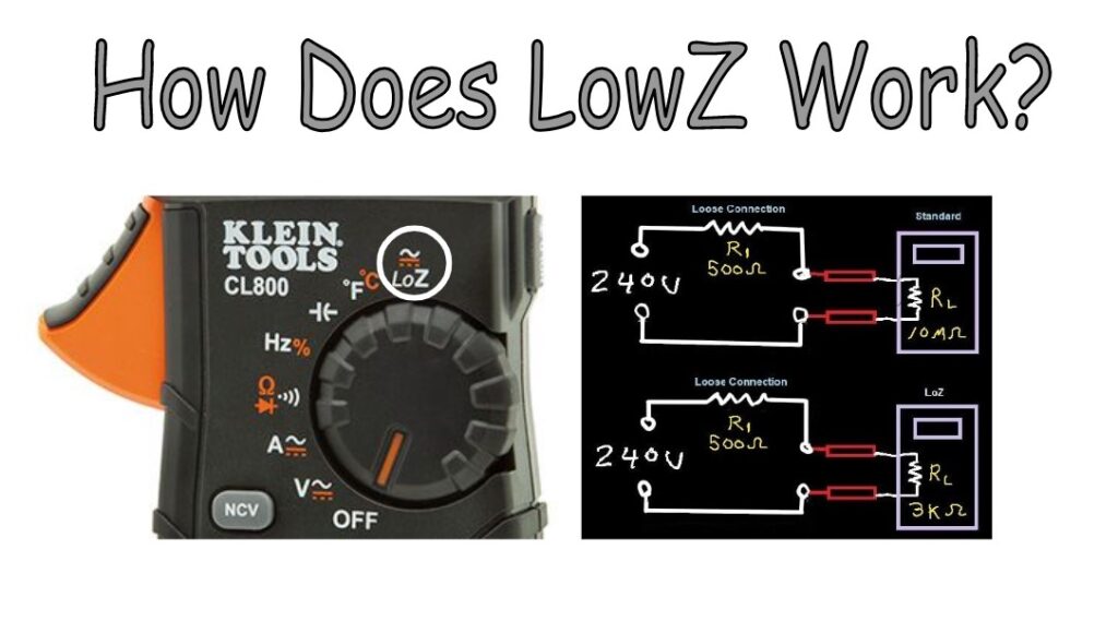
How do LoZ Meters Work?
Some multimeters have a “LoZ” setting, but how does it work and why should you use it instead of the regular AC voltage setting? The LoZ mode places a load on the points you are measuring. This means that when you use LoZ, you are effectively adding impedance or resistance to the circuit. By the end of this blog, you should have a good understanding of the utility that LoZ offers in your diagnostic work.
What does Z stand for?
In this context, “Z” stands for impedance, which is measured in ohms. Impedance, like resistance, is the opposition to current flow but in AC circuits. It can be just resistance, but may also include the effects of capacitance and inductance. (MORE ABOUT IMPEDANCE HERE) In this blog, we will use impedance and resistance interchangeably for simplicity. However, in AC circuits, when voltage or current is present, impedance is the technically correct term to use.
So what’s a LoZ meter?
Typical Meter’s Input Impedance
All voltmeters have an input impedance. That means if you were to connect your Fluke 116 ohmmeter to a Klein voltmeter in AC voltage mode, you would read a resistance such as 10M Ω (10 million ohms) at the input. When you use that voltmeter to read a voltage, you are putting a load on the circuit you are reading. Yes, even 10M Ω puts a load on a circuit – albeit extremely small. The input impedance of your meter interacts with the circuit impedance – which all circuits have. When you’re reading L1 to L2 at a dryer terminal block for example, you should read 240v. The output impedance of the house voltage supply is extremely low – less than 0.1 Ω, which means that the 10M Ω load from your standard voltmeter reading pales in comparison to that 0.1 Ω – and that the 10M Ω load won’t noticeably affect the voltage.
What if L2 had an upstream loose connection and the dryer was not heating? What if that loose connection was 500 Ω ? This is an example of a compromised voltage source. The standard voltmeter input impedance (10M Ω) still pales in comparison to 500 Ω – so the meter won’t put much of load on that circuit either. The LoZ mode puts a more substantial load on the circuit and helps you identify that what is appearing at L2 is actually compromised, because of the upstream 500 Ω.
LoZ and the Voltage Divider
The LoZ feature on your multimeter takes advantage of a “voltage divider” concept. A voltage divider is a phenomenon that occurs when a source voltage divides itself equally across resistances in a series circuit. This concept helps in understanding how the LoZ mode works, and is illustrated below.
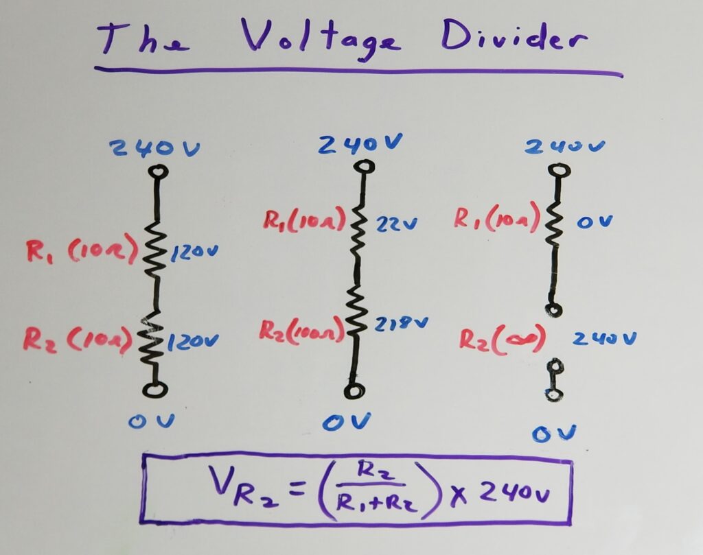
Let’s look at the three cases in the image:
- There are two 10 Ω resistors in series with 240 volts. Since each resistor is the same value, the voltage across each is the same (120 volts). Also, the sum of the voltages across both R1 and R2 together equals the source voltage of 240 volts.
- For the second case, the voltage across each resistor is different. Even so, the sum of the voltage across R1 and R2 still add up to 240 volts. Most importantly though, the resistor with the highest resistance (R2) get the most voltage – which is how voltage dividers work – and most important for field technicians to remember. The next case will take that phenomenon to an extreme with infinite resistance.
- The third case uses infinite resistance for R2. Again, the sum of both voltage add up to the total voltage source of 240 volts. However, R2 gets all the voltage. So as you approach infinity in the equation, R2 approaches the source voltage of 240 volts. The point in this case is that when troubleshooting such a circuit, the highest resistance (including the open circuit – switch, timer contact, relay contact) gets the most or all of voltage.
The conclusion here for each resistance in a series circuit is: “The higher the resistance, the higher the voltage. The lower the resistance, the lower the voltage“.
What is the Input Impedance of a Klein CL800?
Although the standard voltmeter input impedance for the Klein CL800 is around 10M Ω , the LoZ input impedance is much lower – 3K Ω, which is the initial resistance of a thermistor used in the meter. This thermistor by the way, increases in resistance as is warms up (positive temperature coefficient) to protect the meter when measuring large voltages for extended periods. You don’t need to worry about that though when you’re making quick measurements. This 3K Ω resistance is low enough to significantly affect a compromised voltage source (like the one mentioned above with a 500 Ω loose upstream connection). How much will it drop the voltage? Well of course, there’s a formula for that. The good news is, it’s real simple.
*PURCHASE THE KLEIN CL800 LoZ METER HERE*
What Happens When you use LoZ on a Klein CL800?
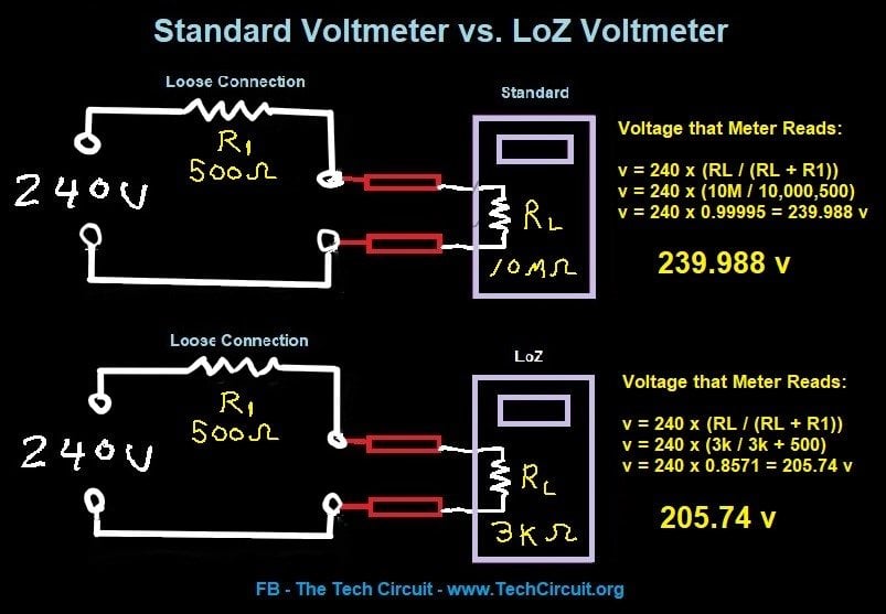
Let’s examine two scenarios for an electric dryer that ran but had no heat. The first scenario involves using the Klein CL800 in its standard AC volts mode to read a circuit with a high-impedance (low-current) L2 and an upstream loose connection of approximately 500 Ω. The second scenario is when you use the LoZ mode.
Both methods employ a “voltage divider” concept to obtain a reading. As you can see, using the standard voltmeter mode would essentially give you a reading of 240V, so you wouldn’t gain insight into what’s happening with the voltage source.
However, when you use the LoZ mode, the voltage divider reveals the problem. This is depicted in the second scenario in the image. The voltage reading you obtain will be 205.74V, which immediately indicates that either L1 or L2 is compromised. You can then use the LoZ function to test L1 to N or L2 to N and determine which line is weak. It is likely that, based on intuition, if the dryer had no heat, the problem is on L2, as the motor typically sources its voltage from L1 to N, and if the issue were with L1, the dryer would likely not have started in the first place.
How to Determine the Upstream Impedance
Using your voltage reading to determine the value of the loose upstream connection may be useful for information for the follow-up electrician. It may help them know what to look for based on what impedance is typical for given failures. Here’s how to do it (As mentioned, I’ll use the term impedance and resistance interchangeably in this blog for simplicity):
With a little algebraic rearrangement of the the standard voltage divider formula, we have: R1 = RL x ((Vs/VL)-1), where R1 is your upstream impedance, RL is your Klein 3KΩ LoZ input impedance, Vs is your source voltage of 240 volts, and VL is your measured voltage across RL with your Klein LoZ meter setting.
So for Case 2 in the image (LoZ), you have R1 = 3000 Ω x ((240v/205.74) – 1) = 499.6 Ω, which matches the example impedance we used.
Ghost Voltages
Ghost voltages are voltages that exist where they shouldn’t. Many technicians use the term “ghost voltages” to refer to compromised voltage sources. However, technically, ghost voltages are those that are inductively or capacitively induced by the proximity to other wiring. One example is when two wires run in parallel, which effectively acts like a capacitor. A capacitor consists of two metal plates separated by a distance and can store an electrical charge. When the voltage changes, or it is an AC voltage, it reduces the overall impedance (actually reactance, but let’s simplify) between the two plates, which can cause a voltage to appear in the nearby wire.
The nearby wire stores this charge because it is floating and has no current path to the circuit reference point. There can also be induced voltages due to the magnetic fields around wires that are in close proximity, similar to how transformers work.
LoZ mode in multimeters provides a relatively low impedance current path to the reference point. This helps “bleed off” these ghost voltages and provides a more realistic reading.
When not to use LoZ
The LoZ function on your meter can generally be used freely. However, there are cases where high resistances are present in a circuit, and using LoZ can result in false readings. Here are a few examples of when not to use LoZ:
- When tracing a circuit with intentionally high resistances: In some circuits, high resistances may be intentionally introduced for specific purposes. If you use LoZ in such cases, it can disrupt the intended behavior of the circuit and provide inaccurate readings or even damage components. One example is with electric dryers that use a voltage divider to derive 120v for the timer motor during the automatic cycle. Typically, a 4.5 K resistance is used to reduce the 240v difference between L1 and L2 by 120v via a voltage divider. If you were to test the voltage (using LoZ) at the midpoint while referencing L2, during this cycle, you would only read about 70v where you should be reading 120v. This is because the LoZ function creates a parallel resistance with with the resistor, that reduces the voltage across it to about 70v and increases the voltage across the timer to about 170v. However, if you use the regular AC voltage function, you will measure approximately 120v.
- Another case when not to use LoZ is when checking for a floating neutral by comparing it to ground. Using LoZ to do this “pulls” neutral and ground together because the meter’s low impedance relative to neutral’s upstream high impedance. Rather, one should use HiZ to perform this test.
- When dealing with circuits involving sensitive electronics (control boards): Sensitive electronic devices or components on control boards may not tolerate the additional load introduced by the LoZ function. It’s important to avoid using LoZ in such situations to prevent any damage or disruption to the circuitry.
So just be aware that in the above cases, LoZ mode can introduce circuit-changing impedance that can yield incorrect readings and throw you off. Here is the full article that details four diagnostic instances where LoZ should NOT be used: https://techcircuit.org/when-not-to-use-a-loz-meter/
Recommended LoZ Meter
The Klein CL800 is an exceptional all-around meter designed specifically for field technicians. This meter offers a comprehensive range of features that cater to the diverse needs of professionals working in the field. One notable feature of the Klein CL800 is its inclusion of LoZ testing for both AC and DC volts, making it a versatile and valuable tool for troubleshooting electrical systems.
Writing informative articles like this one requires a significant amount of time and effort. As a way to support my work, I do receive a commission for any sales made through the following link. Your support is genuinely appreciated, and it allows me to continue providing valuable content.
Summary
This blog discussed the benefits of using the LoZ function to detect both compromised voltage sources and ghost voltages. A compromised voltage source refers to one that is weakened in its ability to supply current. When attempting to draw substantial current from a compromised voltage source, the voltage can significantly drop.
On the other hand, ghost voltages are induced by proximity coupling and are typically found at undefined circuit points with no current flowing through them. Ghost voltages are unpredictable and can appear unexpectedly.
Therefore, it is recommended to use the LoZ function whenever possible to effectively identify compromised voltage sources and mitigate ghost voltages. However, it is important to be aware of specific cases where using LoZ is inappropriate and may yield inaccurate results.
Overall, understanding the advantages and limitations of the LoZ function can greatly assist in diagnosing electrical issues and ensuring accurate voltage measurements. TC
*PURCHASE THE KLEIN CL800 HERE*
“Diverting 10 min/day of social media time towards learning something new, is 5 hours of newfound monthly knowledge.” – SM
To DONATE to the Tech Circuit – CLICK HERE
Alphabetical Links to all Tech Circuit Articles and Blogs – CLICK HERE
Links to all Tech Circuit Cheat Sheets/Field References for Appliance/HVAC Techs – CLICK HEREFor additional electrical and electronics learning material for field techs, visit our homepage at http://www.TechCircuit.org or our Facebook group at https://www.facebook.com/groups/746823709133603, or our YouTube Channel
at https://www.youtube.com/c/TheTechCircuitWe are a participant in the Amazon Services LLC Associates Program, an affiliate advertising program designed to provide a means for us to earn fees by linking to Amazon.com